Lucent Technologies Lineage
®
2000 100A Ferroresonant Rectifier J85503A-1
2 - 10 Product Description
Issue 6 October 1998
Front Panel
Controls and
Indicators
Figure 2-5 shows the front control panel of the J85503A-1,
100-ampere rectifier.
The following list describes the controls and indicators on the
rectifier control panel. These features should be observed and
manually operated during normal rectifier performance. Bold
letters indicate labels that appear on the control panel or inside
the rectifier.
•
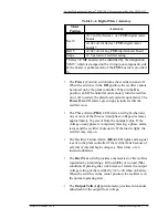
The digital Output meter displays (1) the rectifier output
current when the selector switch is in the Amps position, (2)
the rectifier output voltage when the selector switch is in the
Rect V position, and (3) the plant battery voltage when the
selector switch is in the Batt V position. The default display
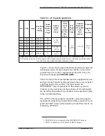
is rectifier output current. Table 2-A gives the accuracy of
this meter in the various positions. The output voltage (Rect
V) accuracy depends on the vintage of the digital meter
board, or circuit module CM3, in the rectifier.
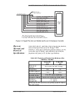
Figure 2-5: Control Panel on the J85503A-1 Rectifier


