Lucent Technologies Lineage
®
2000 100A Ferroresonant Rectifier J85503A-1
5 - 4 Installation
Issue 6 October 1998
DC Output Power
The majority of dc power plants for telecommunication
applications are designed to use single conductor cables (in
parallel for current capacity or to limit voltage drop) supported
on ladder racks. Experience has shown that the use of flexible
cables (welding type cables) makes installation of this type
wiring much simpler. Therefore, the terminals are sized to fit
KS-24194 L2 wire, which is very flexible.
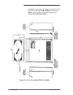
Figure 5-1 shows the dc output conduit hole and alternate hole.
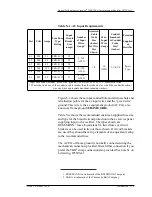
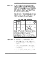
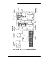
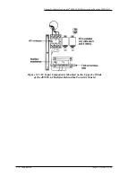
Figure 5-2 shows the dc output wire termination points. Table
5-B specifies the dc output cable size, T&B connectors, and
crimp die. Also see note 57 on J-drawing, J85503A-1.
Installation Tools
The following tools are required for installing rectifiers:
•
Material handling equipment to unload rectifiers at site,
remove them from shipping containers, and place them in
final positions
•
Common electrician's hand tools, including jeweler's
screwdriver, electrical tape, wire cutters and strippers, 14
AWG
to 2
AWG
wire
•
Proper crimping tools and dies for connectors used in the
installation.
Table 5-B: DC Output Requirements
Amps
Output
Wire
Size*
Output
Conduit
Trade Size
(inches)
Connectors
Required
T&B
Crimp
Die
100
#2 AWG
1-1/4
2 studs
(5/16" dia., 7/8"
apart) T&B
54858BE
(2-hole crimp lug)
Green
* Use KS-24194 L2 wire. It is a flexible, stranded copper wire,
rated 600 volts; stranding meets American Society for Testing
and Materials (ASTM) B 172 Class I. This non-halogen,
insulated wire is rated 90°C. The insulation has a
combustibility rating of 28% minimum as determined by
ASTM D2863. Wire sizes were chosen to limit the voltage
drop to 2 volts where the cable loop is approximately 200 feet.


