Lucent Technologies Lineage
®
2000 100A Ferroresonant Rectifier J85503A-1
Issue 6 October 1998
Installation 5 - 11
2. Disconnect ac power from ac distribution service panel
that supplies power to the rectifier.
3. Install fuse holders or circuit breaker for the rectifier in the
ac distribution service panel. Leave circuit breaker in off
position or remove fuses.
4. Install three phase leads and frame ground at service panel
and route conductors to rectifier.
5. Install the connector you prefer onto the frame ground lead
(see “AC Input Power” in Section 5). Use the proper
crimping tool and die for the connector to prevent damage
to equipment. Strip the ends of the three phase leads that
will be installed in the rectifier.
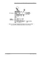
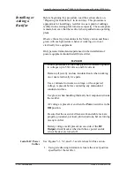
6. Secure phase leads and FRAME GRD lead in rectifier as
shown in Figure 5-3. Install ground lead first. Torque all
frame ground connections and phase connections for Lists
5 and 6 to 20 in-lbs. Torque phase connections to 35 in-lbs
for Lists 1 - 4.
7. Verify that the branch circuit breaker to the rectifier in the
ac service panel is off or fuses are removed. Reenergize ac
service panel. Tag branch circuit breaker or fuse holders to
inform others not to close (turn on) the breaker or insert
fuses. If the branch circuit, (all phase leads plus the frame
ground), is protected by fuses, physically remove the fuses
from the area of the ac service panel.
Install DC Power
Cables
Plant bus bars may carry 52 volts dc. Observe safety warnings
and precautions in Section 4.
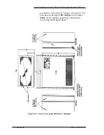
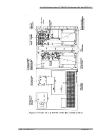
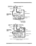
Use Figures 5-1 and 5-2 as references for this section.
1. Turn DC Output circuit breaker on rectifier off (down).
2. Measure the lengths of cable required to run the dc output
from the rectifier to its termination point on the charge bus,
and to run the dc return from the rectifier to its termination
point on the charge ground bus.
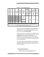
3. Cut cables to length and install crimp connectors. Use the
proper crimping tool and die for the connector to prevent
damage to equipment. See Table 5-B.

