April 17, 2000
Man ual Versio n 1.0
3.9
control came configured for a cushion adjust system, then a wiring diagram should have been provided
as part of the documentation package.
Section 3.5
Hydraulic Overload System Installation
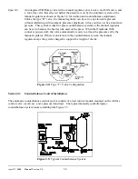
Some press hydraulic overload systems use an air pressure to set up a much greater hydraulic pressure
through an air pump to control the trip point (tonnage) at which the hydraulic overload cylinder will
dump. On these presses the auto-setup card can use an E/P valve (also known as a servo valve) to
actually set the trip point for the hydraulic overload.
These systems vary widely, and it will be necessary for Link to obtain prints of the press hydraulic
overload system in order to determine where to mount control components. If your control came
configured for a hydraulic overload adjust system, then a wiring diagram should have been provided as
part of the documentation package.
Section 3.6
Slide Adjust System Installation
Standard slide adjust systems that set shut height on presses vary widely depending on manufacturer and
age. In general, slide adjust systems are either manually turned by wrenches or levers, or use electric or
air motors to adjust the shut height. The OmniLink automatic slide adjust system can only be used on
presses with motorized slide adjust. Slide adjust motor(s) must be wired to the automatic shut height
adjust module(s) in the OmniLink extended card rack. In addition, either a linear magnetostrictive or a
rotary resolver based transducer must be mounted in such a way as to detect slide adjust position and
wired to the automatic shut height module. Rotary transducers may be used when shafts that turn when
shut height is adjusted are accessible such as a shaft that drives a mechanical shut height indicator.
Linear transducers must be used if no rotating shaft is accessible, but the linear transducer can only be
used on presses with barrel screw type adjustment mechanisms.
Section 3.6.1 Rotary Transducer Mounting
The Link software supports two different types of rotary transducers for the slide adjust system. Both
are based on dual resolvers to provide an absolute position indication. Resolvers are a tough, accurate
rotary position sensor. By using two resolvers mounted in an enclosure with one resolver geared down
relative to the other, a multi-turn resolver (typically around 100 turns) is created.
As mentioned earlier, just about every slide adjust system is different. Some point must be found that
rotates when the slide is adjusted. Some obvious points are the slide adjust motor shaft and the shaft that
drives a dial counter (if present) that indicates slide position. Depending on the press, there may be
other points that can be used. The resolver should be tied in to one of these points - and may need to be
geared up or down. Requirements are:
a) As much as possible, the resolver should be mounted where it will not be submerged in oil,
grease, or other contaminants.
b) The total slide travel from maximum shut height to minimum shut height
must not exceed
the
number of turns of the resolver. If , for example, a 100 turn resolver is used, the total slide travel
from maximum to minimum
must not result
in more than 100 turns at the resolver.
Содержание OmniLink 5000
Страница 5: ...April 17 2000 Manual Versio n 1 0 iv...
Страница 38: ...April 17 2000 Manual Versio n 1 0 4 14...
Страница 63: ...April 17 2000 Manual Versio n 1 0 B 2 Figure B 2 Typical Cushion Wiring Diagram...
Страница 64: ...April 17 2000 Manual Versio n 1 0 B 3 Figure B 3 Conceptual Dual Resolver Mounting...
Страница 65: ...April 17 2000 Manual Versio n 1 0 B 4 Figure B 4 Typical AMCI Dual Resolver Wiring Diagram...
Страница 66: ...April 17 2000 Manual Versio n 1 0 B 5 Figure B 5 Typical GEMCO Dual Resolver Wiring Diagram...
Страница 67: ...April 17 2000 Manual Versio n 1 0 B 6 Figure B 6 Conceptual Linear Transducer Mounting...
Страница 68: ...April 17 2000 Manual Versio n 1 0 B 7 Figure B 7 Typical GEMCO Linear Transducer Wiring...
Страница 69: ...April 17 2000 Manual Versio n 1 0 B 8 Figure B 8 Typical MTS Temposonics II Linear Transducer Wiring...
Страница 71: ...April 17 2000 Manual Versio n 1 0 B 10...
Страница 73: ...April 17 2000 Manual Versio n 1 0 C 2...


