April 17, 2000
Man ual Versio n 1.0
4.3
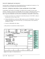
There are several parameters that must be configured in this screen. The editing cursor indicates which
parameter is currently selected. Softkey 1 (the uppermost vertical softkey) will change its description
based on the parameter and, when pressed, allows the currently selected parameter to be changed. The
up and down arrow keys move the editing cursor from one parameter to another.
See Appendix A for
examples of setting up each kind of system.
The features of this screen are:
Help
The “Help” box at the bottom of the screen changes depending on the parameter
that the editing cursor is currently on. It gives a short version of how the
parameter is used.
Air Slot
Corresponds to the physical slot number (AS1 in the example of Figure 4.2)
selected for configuration on the auto-setup card. AS5 and AS6 do not exist but
are reserved for future expansion. The “NEXT AIR SLOT” softkey will cycle
through the available slots in the system. Note that “AS7" is built in to the base
auto-setup board and is always installed.
Hardware Detected
For counterbalances and cushions this should be “Fill/Dump” (referring to the
control method for the board). For hydraulic overloads this should be “0-10Volt
Out”. If there is no board installed in that slot the board will be “None Detected”.
Air Pressure
Gives a readout of the current pressure detected by the pressure transducer based
on the transducer type selected. Note that when the transducer type is changed,
this pressure will also change even though the actual air pressure stays the same.
This value can not be changed by the user. It is reported in this screen for
convenience.
Name
Press the “CHANGE NAME” soft key repetitively to cycle through and select the
available names for the module in the slot which you are configuring (Counter-
Balance #1, Counter-Balance #2, Cushion #1, Cushion #2, Cushion #3, Cushion
#4, Hydraulic Overload, Not Configured). Stop when the desired name appears.
Mode
Use the “CHANGE MODE” soft key to cycle the status from
ON
to
MAN
to
OFF
and back to
ON
.
ON
means the OmniLink 5000 will automatically adjust the air
pressure when a job is recalled to the air pressure associated with that job.
MAN
means the OmniLink 5000 will automatically adjust the air pressure, but the
pressure can only be changed from the Auto Setup screen by entering the desired
air pressure. A recalled job will NOT change the pressure if you configure the
module to
MAN
.
OFF
means the OmniLink 5000 will not control the air
pressure. This value should typically be set to
ON
.
Max. Pressure
This value should be set to the maximum operating air pressure at which the
counterbalance, cushion, or hydraulic overload is designed to operate.
For counterbalances, this is the pressure which counterbalances the heaviest upper
die the press is designed to accommodate. The press counterbalance table
(typically mounted on the press) or the press manual should give this value.
Содержание OmniLink 5000
Страница 5: ...April 17 2000 Manual Versio n 1 0 iv...
Страница 38: ...April 17 2000 Manual Versio n 1 0 4 14...
Страница 63: ...April 17 2000 Manual Versio n 1 0 B 2 Figure B 2 Typical Cushion Wiring Diagram...
Страница 64: ...April 17 2000 Manual Versio n 1 0 B 3 Figure B 3 Conceptual Dual Resolver Mounting...
Страница 65: ...April 17 2000 Manual Versio n 1 0 B 4 Figure B 4 Typical AMCI Dual Resolver Wiring Diagram...
Страница 66: ...April 17 2000 Manual Versio n 1 0 B 5 Figure B 5 Typical GEMCO Dual Resolver Wiring Diagram...
Страница 67: ...April 17 2000 Manual Versio n 1 0 B 6 Figure B 6 Conceptual Linear Transducer Mounting...
Страница 68: ...April 17 2000 Manual Versio n 1 0 B 7 Figure B 7 Typical GEMCO Linear Transducer Wiring...
Страница 69: ...April 17 2000 Manual Versio n 1 0 B 8 Figure B 8 Typical MTS Temposonics II Linear Transducer Wiring...
Страница 71: ...April 17 2000 Manual Versio n 1 0 B 10...
Страница 73: ...April 17 2000 Manual Versio n 1 0 C 2...


