April 17, 2000
Man ual Versio n 1.0
2.6
Step A:
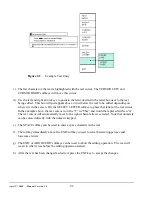
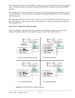
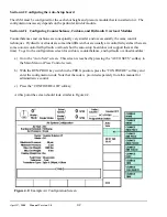
Select the restricted item. In the example shown in Figure 2.2 the restricted item is Slide
Adjust #1 setpoint. Once the parameter is selected then Softkey # 1, the upper vertical
softkey (Softkey # 1 is highlighted in Figure 2.2) , will display the legend “SELECT”.
Step B:
A list of users that have access to this restricted item will appear. In the example shown in
Figure 2.2 only User Number One, User Number Two, and User Number Five have access to
this restricted parameter. The system may have several more users, but the three users listed
on the screen are the only users that have access to change an Auto Setup Setting . The user
must use the arrow keys to position the cursor on his user name. After placing the cursor on
the correct name, the user must press the SELECT softkey. The SELECT softkey must be
pressed even if there is only one user name displayed.
Step C:
The display will show the selected user name and request the user password. The user must
enter the correct password and then press the ENT key.
Step D:
Upon entry of the correct password, the user will be allowed access to the restricted item. In
the example shown in Figure 2.2, the user will have access to change the Slide Adjust #1
setpoint.
After performing the steps listed above, the user will be logged in to the password system. The user will
have access to all restricted items that have been designated for his access. This access will remain until
the user performs a log out or until the user is automatically logged out.
The user can log out by using the ACC key. This key will directly switch the display to the Quick
Access screen. The “LOGOUT” soft key legend will appear along the bottom of the screen. If the
operator presses this key, he will log out. He will no longer have access to the restricted items, unless he
repeats steps A through D.
In addition to the manual log out, the system contains an automatic logout. The intent of automatic log
out is to reduce the possibility of users other than the intended user having access to restricted items. If
there were no provisions for automatic log out and a user forgot to manually log out, all restricted items
to which the user had been designated for access would be available from the log in time until power
was removed from the OmniLink control. This presents the possibility of users other than the intended
user having access to restricted items. Automatic log out is based upon both time and press strokes.
During system configuration automatic Access Timeout parameters are entered. An automatic access
timeout time and automatic access timeout strokes are entered. The time entered is the amount of time
after the last key stroke that will be allowed before the system will automatically log out the user. For
example, if the automatic access timeout is set to 60 seconds, the user will be logged out 60 seconds
after the last key stroke. If the user presses a key before the 60 seconds have elapsed, a new 60 second
cycle will be started. The number of strokes that are entered is the number of press strokes after the last
key stroke that will be allowed before the system automatically logs out the user. For example, if the
automatic timeout is set to 10 strokes, the user will be logged out when the press completes ten strokes
after the last key stroke. If the user presses a key before 10 strokes have been completed, a new 10
stroke cycle will be started.
Содержание OmniLink 5000
Страница 5: ...April 17 2000 Manual Versio n 1 0 iv...
Страница 38: ...April 17 2000 Manual Versio n 1 0 4 14...
Страница 63: ...April 17 2000 Manual Versio n 1 0 B 2 Figure B 2 Typical Cushion Wiring Diagram...
Страница 64: ...April 17 2000 Manual Versio n 1 0 B 3 Figure B 3 Conceptual Dual Resolver Mounting...
Страница 65: ...April 17 2000 Manual Versio n 1 0 B 4 Figure B 4 Typical AMCI Dual Resolver Wiring Diagram...
Страница 66: ...April 17 2000 Manual Versio n 1 0 B 5 Figure B 5 Typical GEMCO Dual Resolver Wiring Diagram...
Страница 67: ...April 17 2000 Manual Versio n 1 0 B 6 Figure B 6 Conceptual Linear Transducer Mounting...
Страница 68: ...April 17 2000 Manual Versio n 1 0 B 7 Figure B 7 Typical GEMCO Linear Transducer Wiring...
Страница 69: ...April 17 2000 Manual Versio n 1 0 B 8 Figure B 8 Typical MTS Temposonics II Linear Transducer Wiring...
Страница 71: ...April 17 2000 Manual Versio n 1 0 B 10...
Страница 73: ...April 17 2000 Manual Versio n 1 0 C 2...

