April 17, 2000
Man ual Versio n 1.0
3.7
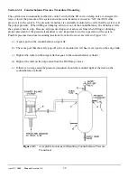
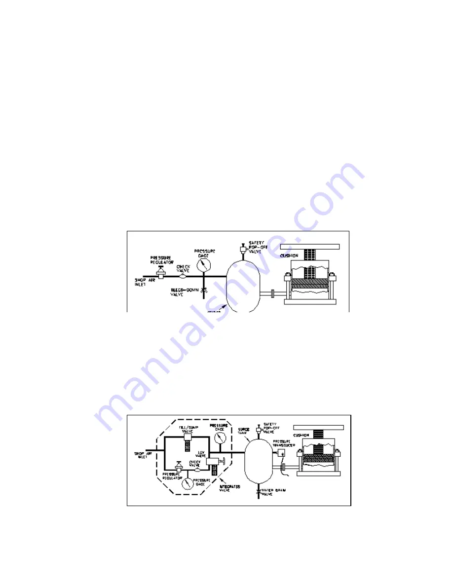
Figure 3.9:
Typical Standard Cushion System
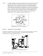
Figure 3.10:
Cushion System with Type “B” Integrated
Valve.
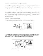
Section 3.3.2 Counterbalance Air Valve System Mounting
The mounting location of the valve system is not critical. Consideration should be given, however, to
ease of maintenance, plumbing, and wiring when choosing the mounting location. Also note that
sometimes the check valve in the original system may be up at the surge tank itself. The check valve
in
the original system
must
be removed for the automatic system to work properly.
Section 3.3.3 Counterbalance System Wiring
Refer to Appendix B, Figure B.1, for typical wiring of the counterbalance valve and pressure transducer.
Note that the auto-select connection is used only for a type “C” valve. For type “A” valves, the auto-
select connection from pin 2 of the counterbalance module is not required. If you order an OmniLink
control with a counterbalance adjust system, then a wiring diagram will be provided as part of the
documentation package.
Section 3.4
Cushion System Installation
The typical manually adjustable press cushion system looks something like Figure 3.9.
For automatic control, the pressure regulator and check valve are replaced with an air valve system.
Figure 3.10 shows a system using a Type “B” valve as described in section 3.2. Type “A” and “C”
valves may also be used. A pressure transducer is used to monitor the air pressure.
Содержание OmniLink 5000
Страница 5: ...April 17 2000 Manual Versio n 1 0 iv...
Страница 38: ...April 17 2000 Manual Versio n 1 0 4 14...
Страница 63: ...April 17 2000 Manual Versio n 1 0 B 2 Figure B 2 Typical Cushion Wiring Diagram...
Страница 64: ...April 17 2000 Manual Versio n 1 0 B 3 Figure B 3 Conceptual Dual Resolver Mounting...
Страница 65: ...April 17 2000 Manual Versio n 1 0 B 4 Figure B 4 Typical AMCI Dual Resolver Wiring Diagram...
Страница 66: ...April 17 2000 Manual Versio n 1 0 B 5 Figure B 5 Typical GEMCO Dual Resolver Wiring Diagram...
Страница 67: ...April 17 2000 Manual Versio n 1 0 B 6 Figure B 6 Conceptual Linear Transducer Mounting...
Страница 68: ...April 17 2000 Manual Versio n 1 0 B 7 Figure B 7 Typical GEMCO Linear Transducer Wiring...
Страница 69: ...April 17 2000 Manual Versio n 1 0 B 8 Figure B 8 Typical MTS Temposonics II Linear Transducer Wiring...
Страница 71: ...April 17 2000 Manual Versio n 1 0 B 10...
Страница 73: ...April 17 2000 Manual Versio n 1 0 C 2...

