April 17, 2000
Man ual Versio n 1.0
A.4
The pressure transducer installed on the system is a Setra model C206 that has a pressure range of 0 to
250 psi and an output of 4 to 20 ma.
An SMC ITV2050-31T2S4 servo-valve will be used to control the pressure. This valve is 0-130 psi
with a 0-10V input.
Now we go to the “Auto Sets” screen and with the RUN/PROG switch in PROG hit the “CONFIGURE”
softkey. After typing the configuration code, we press the “CONFIGURE AIR” softkey.
Since the hydraulic overload is wired in at “AS7", if the slot reported on the screen in not already “AS7",
we hit the “NEXT AIR SLOT” softkey until it is. The hardware detected should be “0 - 10 Volt Out”.
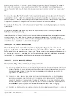
The first thing we must configure is the “Name” of the system. The cursor should already be on the
“Name” line so we check to see if the name is already “Hydraulic Overload". If not, the “CHANGE
NAME” softkey allows us to cycle through the systems.
Using the arrow keys, we move the cursor to the “Transducer Type” line. Looking at table 4.1, we see
that the transducer type for any model pressure transducer with a 250 psi pressure range and a 4 to 20 ma
output is “Type 3". We hit the “CHANGE TYPE” softkey select Type 3 from the list that appears.
When the proper type is selected, the “Air Pressure” line should change to read the pressure currently in
the hydraulic overload system.
Next we use the arrow keys to move the editing cursor to the “Maximum Pressure” line. From the
information we already gathered, we enter 80 psi.
Going to the “Minimum Pressure” line, we enter 20 psi.
“Max. Trip Point” should be the tonnage trip point at the Max Pressure (80 psi in this case) so we enter
400 tons. Note that units to the right of the number are also an editable parameter. When the editing
cursor is placed on the Max Trip Point units, we can press the “CHANGE UNIT” softkey to get a list of
supported units. The units can be pounds, kilograms, tons, or metric tons. A hydraulic overload will
typically use tons and that is what we select. Note that the units for minimum and maximum trip point
will always be the same, but will not necessarily be the same as the “Display Trip As” units. This
allows us to enter the minimum and maximum trip points in whatever units the name plate uses, but
operate the press in a different set of units.
“Min. Trip Point” should be the tonnage trip point at the Min Pressure ( 20 psi in this case) so we enter
100 tons.
The “Display Trip As” units we set to tons.
The “Fault Time” we leave at 20 seconds.
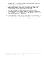
The “Valve Type” is set to “6". This value comes from table 4.2 for the type of servo valve we have.
The “Tolerance” is left at the default 2 psi.
Содержание OmniLink 5000
Страница 5: ...April 17 2000 Manual Versio n 1 0 iv...
Страница 38: ...April 17 2000 Manual Versio n 1 0 4 14...
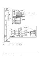
Страница 63: ...April 17 2000 Manual Versio n 1 0 B 2 Figure B 2 Typical Cushion Wiring Diagram...
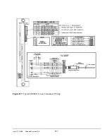
Страница 64: ...April 17 2000 Manual Versio n 1 0 B 3 Figure B 3 Conceptual Dual Resolver Mounting...
Страница 65: ...April 17 2000 Manual Versio n 1 0 B 4 Figure B 4 Typical AMCI Dual Resolver Wiring Diagram...
Страница 66: ...April 17 2000 Manual Versio n 1 0 B 5 Figure B 5 Typical GEMCO Dual Resolver Wiring Diagram...
Страница 67: ...April 17 2000 Manual Versio n 1 0 B 6 Figure B 6 Conceptual Linear Transducer Mounting...
Страница 68: ...April 17 2000 Manual Versio n 1 0 B 7 Figure B 7 Typical GEMCO Linear Transducer Wiring...
Страница 69: ...April 17 2000 Manual Versio n 1 0 B 8 Figure B 8 Typical MTS Temposonics II Linear Transducer Wiring...
Страница 71: ...April 17 2000 Manual Versio n 1 0 B 10...
Страница 73: ...April 17 2000 Manual Versio n 1 0 C 2...


