


April 17, 2000
Man ual Versio n 1.0
3.3
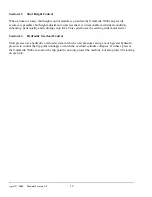
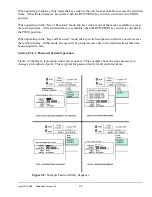
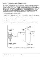
Figure 3.2:
Type “A” Valve Configuration
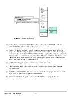
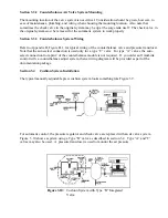
Figure 3.3:
Type “B” Valve Configuration
Section 3.2
Valve Systems
Counterbalance and cushion systems are very similar in the way they are controlled. Three basic
integrated valve configurations are available from Link to be used with the OmniLink 5000 ASM. For
clarity in the following sections, these valve configurations are defined here.
Type “A”
An integrated Fill/Dump Valve as shown in Figure 3.2. This valve has the advantage of
simple straight through piping with all pilot pressures run internally and is easily
mounted. It may be used for air cushion and air counterbalance control. This is the least
expensive of the three valves. Leaks in cushion and counterbalance systems will cause
loss of pressure in these systems when either control power is off or supply pressure is
absent. However, the control must be turned back on and pressure re-established before
the press will stroke.
Type “B”
An integrated Fill/Dump valve with a manual regulator, check valve, and LOX valve in
parallel as shown in Figure 3.3 for cushion, but not counterbalance, adjustment. This
valve adds a parallel manual regulator system to the Type “A” valve, which may be set
to prevent the air pressure in the cushion from going below a
minimum
value set by the
manual regulator (as long as there is shop air pressure). This prevents cushion drift down
when control power is off with its associated lost die pins below the press bolster and lost
time while they are recovered. This valve also allows the cushions to be adjusted using
the manual regulator path if the automatic system fails, allowing the press to be operated
until the automatic system is restored. When the automatic system is on, the manual
regulator on this valve system
must not
be set higher than the lowest pressure that the
automatic system is to provide, because the automatic valves will try to dump while the
manual regulator fills if the automatic setpoint is lower than the manual regulator
pressure.
Содержание OmniLink 5000
Страница 5: ...April 17 2000 Manual Versio n 1 0 iv...
Страница 38: ...April 17 2000 Manual Versio n 1 0 4 14...
Страница 63: ...April 17 2000 Manual Versio n 1 0 B 2 Figure B 2 Typical Cushion Wiring Diagram...
Страница 64: ...April 17 2000 Manual Versio n 1 0 B 3 Figure B 3 Conceptual Dual Resolver Mounting...
Страница 65: ...April 17 2000 Manual Versio n 1 0 B 4 Figure B 4 Typical AMCI Dual Resolver Wiring Diagram...
Страница 66: ...April 17 2000 Manual Versio n 1 0 B 5 Figure B 5 Typical GEMCO Dual Resolver Wiring Diagram...
Страница 67: ...April 17 2000 Manual Versio n 1 0 B 6 Figure B 6 Conceptual Linear Transducer Mounting...
Страница 68: ...April 17 2000 Manual Versio n 1 0 B 7 Figure B 7 Typical GEMCO Linear Transducer Wiring...
Страница 69: ...April 17 2000 Manual Versio n 1 0 B 8 Figure B 8 Typical MTS Temposonics II Linear Transducer Wiring...
Страница 71: ...April 17 2000 Manual Versio n 1 0 B 10...
Страница 73: ...April 17 2000 Manual Versio n 1 0 C 2...