April 17, 2000
Man ual Versio n 1.0
A.7
Now it is time to hit the “AUTO ADJUST” softkey. The slide moves up past 14.000 (the slide setpoint
we entered in the operation screen) and stops momentarily at 14.025. It then comes back down and
stops at 13.996. The “Pulse Distance” value is set too high. What should have happened is that the slide
would go over 14.000, come back down to a position just over 14.000 - say 14.003 - and then pulse into
position at 14.000. Since we went under our setpoint by .004 inches, we change the “Pulse Distance” to
.017 inches (adding .004 for the undershoot plus .003 for good measure to the original value of .010).
Now when we hit the “AUTO ADJUST” softkey the slide travels first to 14.039, stops momentarily,
travels down to 14.003, and pulses the slide into position at 14.000 - perfect.
See section 5.1 for further details on slide adjust operation.
Section A.5
Example Rotary Slide Adjust Configuration
This example assumes the rotary slide adjust system has been wired to the option board at “SS1". First,
some information needs to be gathered.
A 100 turn AMCI series dual resolver is mounted on the press slide.
From the nameplate on the press or the press manual, we find that the minimum shut height is 12.500
inches and the maximum shut height is 16.000 inches.
Now we go to the “Auto Sets” screen and with the RUN/PROG switch in PROG hit the “CONFIGURE”
softkey. After typing the configuration code, we press the “CONFIGURE SLIDE” softkey.
Since the slide adjust system is wired in at “SS1", if the slot reported on the screen in not already
“AS1", we hit the “NEXT SLIDE SLOT” softkey until it is. The hardware detected should be “Rotary
Transducer”.
The first thing we must configure is the “Name” of the system. The cursor should already be on the
“Name” line so we check to see if the name is already “Slide Adjust #1". If not, the “CHANGE NAME”
softkey allows us to cycle through the systems.
During initial slide setup, the “Mode” of the slide needs to be set to “OFF”. Moving the editing cursor
to the mode parameter, we hit the “CHANGE MODE” softkey until the mode reads “OFF”.
Before we set anything further, we need to choose the units for the slide system. Moving the editing
cursor to the “Shut Height Units” parameter, we use the “CHANGE UNIT” softkey to set the units to
inches for this example. Note that this sets the units for all other shut height position or distance
parameters on this screen and during calibration. After calibration, the units can be changed, if desired.
The “Upper Limit” and “Lower Limit” we set to 16.000 inches and 12.500 inches respectively. When
the mode if the system is “OFF”, these limits are not enforced. This allows us to check the operation of
the mechanical limit switches.
The “Tolerance”, “Pulse Distance”, “Pulse Time”, and “Lock Time” are left at .004, .010, .03, and 0
respectively - the default values. We may find these have to be changed later on.
Содержание OmniLink 5000
Страница 5: ...April 17 2000 Manual Versio n 1 0 iv...
Страница 38: ...April 17 2000 Manual Versio n 1 0 4 14...
Страница 63: ...April 17 2000 Manual Versio n 1 0 B 2 Figure B 2 Typical Cushion Wiring Diagram...
Страница 64: ...April 17 2000 Manual Versio n 1 0 B 3 Figure B 3 Conceptual Dual Resolver Mounting...
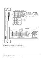
Страница 65: ...April 17 2000 Manual Versio n 1 0 B 4 Figure B 4 Typical AMCI Dual Resolver Wiring Diagram...
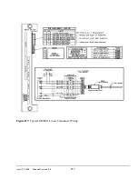
Страница 66: ...April 17 2000 Manual Versio n 1 0 B 5 Figure B 5 Typical GEMCO Dual Resolver Wiring Diagram...
Страница 67: ...April 17 2000 Manual Versio n 1 0 B 6 Figure B 6 Conceptual Linear Transducer Mounting...
Страница 68: ...April 17 2000 Manual Versio n 1 0 B 7 Figure B 7 Typical GEMCO Linear Transducer Wiring...
Страница 69: ...April 17 2000 Manual Versio n 1 0 B 8 Figure B 8 Typical MTS Temposonics II Linear Transducer Wiring...
Страница 71: ...April 17 2000 Manual Versio n 1 0 B 10...
Страница 73: ...April 17 2000 Manual Versio n 1 0 C 2...


