April 17, 2000
Man ual Versio n 1.0
4.1
NOTE!
An access code is required to reach the configuration menus of the
OmniLink 5000 press control. The code is provided separately from this
manual for administrative control.
WARNING! Only qualified employees who are authorized by the user should
configure the automatic set-up module. Failure to properly configure
and calibrate the module can result in machine damage which, in
turn, may result in injury or death to persons.
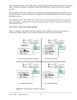
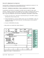
Figure 4.1:
Factory Configuration Parameters
Section 4.
Configuration
After the ASM is installed (see section 3.1), it must be configured to work with the press. Configuration
consists of several steps that depend on the options selected for the ASM.
Section 4.1
Setting up the OmniLink 5000 for the Auto-Setup Module
The OmniLink 5000 press control must be “told” that the 5000-10 ASM is installed in the card rack.
If the module was installed at Link as part of an OmniLink 5000 package, this step will already be done
and configuration should proceed with section 4.2.
a) Go to the Press Control (P/C) screen.
b) With the RUN/PROG key switch in the PROG position, press the “CONFIGURE” softkey and
enter the configuration access code.
c) Press the “MACHINE PARAMETERS” softkey.
d) Press the “FACTORY
CONFIG” softkey. The
screen should now be
similar to Figure 4.1.
e) Use the up and down arrow
keys on the operator
terminal to put the cursor on
the “Automatic Setup” row
and enter “001". If this
parameter is “000" the
OmniLink 5000 won’t
recognize and respond to
the ASM
f) Press the “EXIT” softkey
until the “Press Control”
screen reappears.
Содержание OmniLink 5000
Страница 5: ...April 17 2000 Manual Versio n 1 0 iv...
Страница 38: ...April 17 2000 Manual Versio n 1 0 4 14...
Страница 63: ...April 17 2000 Manual Versio n 1 0 B 2 Figure B 2 Typical Cushion Wiring Diagram...
Страница 64: ...April 17 2000 Manual Versio n 1 0 B 3 Figure B 3 Conceptual Dual Resolver Mounting...
Страница 65: ...April 17 2000 Manual Versio n 1 0 B 4 Figure B 4 Typical AMCI Dual Resolver Wiring Diagram...
Страница 66: ...April 17 2000 Manual Versio n 1 0 B 5 Figure B 5 Typical GEMCO Dual Resolver Wiring Diagram...
Страница 67: ...April 17 2000 Manual Versio n 1 0 B 6 Figure B 6 Conceptual Linear Transducer Mounting...
Страница 68: ...April 17 2000 Manual Versio n 1 0 B 7 Figure B 7 Typical GEMCO Linear Transducer Wiring...
Страница 69: ...April 17 2000 Manual Versio n 1 0 B 8 Figure B 8 Typical MTS Temposonics II Linear Transducer Wiring...
Страница 71: ...April 17 2000 Manual Versio n 1 0 B 10...
Страница 73: ...April 17 2000 Manual Versio n 1 0 C 2...


