April 17, 2000
Man ual Versio n 1.0
D.1
Note!
Step 1
MUST
be done even if a LOX valve is opened in step 2 since the
control may try to pressurize the system using the Fill/Dump valve if the
power is on!
Appendix D Lockout Procedure For Air Controlled Systems
Section D.1
General Lockout Considerations
The OmniLink 5000 auto-setup card automatically controls pressures in cushions and counterbalances.
Because of this there are special considerations to keep in mind when locking an air system out (at 0
pressure).
Note that cushions can be vented to zero pressure and the press will be allowed to run. A counterbalance
that has been vented to zero pressure, however, is considered a stop condition by the press control.
While a type “A” valve has only integrated Fill/Dump valves, the type “B”, and “C” integrated air
valves (See Section 3.1 for a discussion of valve types) that Link uses to control air pressure on
cushions and counterbalances has a manual as well as an automatic section. The manual section for
these valves looks like a typical manual air pressure control with a regulator followed by a check valve.
There is a pressure gauge (“G1”) after the regulator but
before
the check valve, and a gauge (“G2”) at
the output air port
after
the check valve. When raising the pressure by turning the manual regulator “up”
the pressure forces the check valve open and gauge “G1” will be approximately equal to gauge “G2”.
However when lowering the pressure at the manual regulator, the check valve will prevent the actual
output pressure from going down (assuming there are no leaks). A LOX valve on the output is used to
blow down the system to lower the pressure. In either case, gauge “G2” shows the true pressure in the
counterbalance or cushion.
The automatic section of type “B” and “C” valves (and the only section of type “A” valves) consists of a
fill valve and a dump valve. A transducer mounted on the counterbalance surge tank or cushion
electronically reports the pressure of the system to the auto-setup board. If the pressure is too low the
fill valve puts more air in the system. If the pressure is too high the dump valve vents air to atmosphere.
Section D.2
Valve Type “A” Lockout Procedure
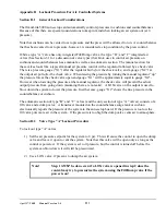
To lock out type “A” valves:
1) Set the air pressure setpoint for the system to 0 psi. This will cause the control to open the dump
valve and leave it open to vent the system. Note that this valve will be open only as long as the
control is powered. If the system is set to 0 pressure, but the control is turned off before the
system can blow down, it will still be pressurized.
2) Use a LOX valve, if present, to dump the air system.
Содержание OmniLink 5000
Страница 5: ...April 17 2000 Manual Versio n 1 0 iv...
Страница 38: ...April 17 2000 Manual Versio n 1 0 4 14...
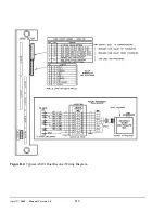
Страница 63: ...April 17 2000 Manual Versio n 1 0 B 2 Figure B 2 Typical Cushion Wiring Diagram...
Страница 64: ...April 17 2000 Manual Versio n 1 0 B 3 Figure B 3 Conceptual Dual Resolver Mounting...
Страница 65: ...April 17 2000 Manual Versio n 1 0 B 4 Figure B 4 Typical AMCI Dual Resolver Wiring Diagram...
Страница 66: ...April 17 2000 Manual Versio n 1 0 B 5 Figure B 5 Typical GEMCO Dual Resolver Wiring Diagram...
Страница 67: ...April 17 2000 Manual Versio n 1 0 B 6 Figure B 6 Conceptual Linear Transducer Mounting...
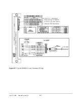
Страница 68: ...April 17 2000 Manual Versio n 1 0 B 7 Figure B 7 Typical GEMCO Linear Transducer Wiring...
Страница 69: ...April 17 2000 Manual Versio n 1 0 B 8 Figure B 8 Typical MTS Temposonics II Linear Transducer Wiring...
Страница 71: ...April 17 2000 Manual Versio n 1 0 B 10...
Страница 73: ...April 17 2000 Manual Versio n 1 0 C 2...


