April 17, 2000
Man ual Versio n 1.0
A.1
Appendix A
Configuration Examples
This section of the manual will go though an example setup of each kind of system on a “typical” press.
Each example assumes that the hardware installation has been completed and the system is ready for
configuration.
The following examples assume the access system is using “Key Only” mode as described in section 2.
Other modes may require entering a user code to change certain parameters.
Section A.1
Example Counterbalance Configuration
This example assumes the counterbalance system has been wired to the option board at “AS1". First,
some information needs to be gathered.
From the press counterbalance table mounted on the frame of the machine (or found in the press
manual), we find that at zero die weight, the counterbalance pressure should be 25 psi. The maximum
upper die weight for our example press is 7500 pounds. At that weight, the table says the pressure
should be 78 psi.
The pressure transducer installed on the system is a Setra model C206 that has a pressure range of 0 to
250 psi and an output of 4 to 20 ma.
A type “C” integrated valve controls the pressure (see section 3.1 for a discussion of valve types).
Now we go to the “Auto Sets” screen and with the RUN/PROG switch in PROG hit the “CONFIGURE”
softkey. After typing the configuration code, we press the “CONFIGURE AIR” softkey.
Since the counterbalance is wired in at “AS1", if the slot reported on the screen in not already “AS1", we
hit the “NEXT AIR SLOT” softkey until it is. The hardware detected should be “Fill/Dump”.
The first thing we must configure is the “Name” of the system. The cursor should already be on the
“Name” line so we check to see if the name is already “Counter-Balance #1". If not, place the editing
cursor on the name and press the “CHANGE NAME” softkey to cycle through the systems.
Using the arrow keys, we move the editing cursor to the “Transducer Type” line. Looking at table 4.1,
we see that the transducer type for any model pressure transducer with a 250 psi pressure range and a 4
to 20 ma output is “Type 3” . We hit the “CHANGE TYPE” softkey and select Type 3 from the list that
appears. When the proper type is selected, the “Air Pressure” line should change to read the pressure
currently in the counterbalance system.
Next we use the arrow keys to move the editing cursor to the “Maximum Pressure” line. Since we found
earlier that the pressure used to balance the heaviest die the press supports is 78 psi, we hit the
“CHANGE MAX PRES” softkey and key in this value.
Going to the “Minimum Pressure” line, we enter in 25 psi, the value that balances only the slide.
Next, “Max. Die Weight” is entered as 7500, the weight counterbalanced at the maximum air pressure.
Содержание OmniLink 5000
Страница 5: ...April 17 2000 Manual Versio n 1 0 iv...
Страница 38: ...April 17 2000 Manual Versio n 1 0 4 14...
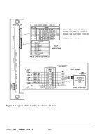
Страница 63: ...April 17 2000 Manual Versio n 1 0 B 2 Figure B 2 Typical Cushion Wiring Diagram...
Страница 64: ...April 17 2000 Manual Versio n 1 0 B 3 Figure B 3 Conceptual Dual Resolver Mounting...
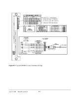
Страница 65: ...April 17 2000 Manual Versio n 1 0 B 4 Figure B 4 Typical AMCI Dual Resolver Wiring Diagram...
Страница 66: ...April 17 2000 Manual Versio n 1 0 B 5 Figure B 5 Typical GEMCO Dual Resolver Wiring Diagram...
Страница 67: ...April 17 2000 Manual Versio n 1 0 B 6 Figure B 6 Conceptual Linear Transducer Mounting...
Страница 68: ...April 17 2000 Manual Versio n 1 0 B 7 Figure B 7 Typical GEMCO Linear Transducer Wiring...
Страница 69: ...April 17 2000 Manual Versio n 1 0 B 8 Figure B 8 Typical MTS Temposonics II Linear Transducer Wiring...
Страница 71: ...April 17 2000 Manual Versio n 1 0 B 10...
Страница 73: ...April 17 2000 Manual Versio n 1 0 C 2...


