April 17, 2000
Man ual Versio n 1.0
3.6
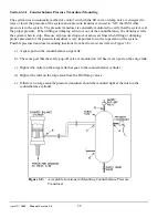
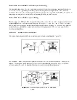
Figure 3.8:
Acceptable Locations for Mounting Counterbalance Pressure
Transducer.
Section 3.3.1 Counterbalance Pressure Transducer Mounting
The system uses an automatic method of control in which the fill valve or dump valve is energized to
raise or lower the pressure of the system and a pressure transducer is used to “tell” the ASM what
pressure is in the system. The pressure transducer is constantly monitored to verify that the system is at
the proper pressure. When filling or dumping air into or out of the counterbalance, the transducer tells
the system when to stop. Because air pressure drops occur across air lines when filling or dumping,
proper placement of the pressure transducer is very important for correct operation of the system.
Possible pressure transducer mounting locations from best to worst are (refer to Figure 3.8):
a) A spare port on the counterbalance surge tank.
b) The same port that the safety pop-off valve is mounted on if it has its own port on the surge tank.
c) Right at the outlet on the surge tank that goes to the counterbalance cylinder.
d) Right at the inlet on the surge tank from the Fill/Dump valves.
e) If there is no surge tank the pressure transducer should be mounted right at the inlet on the
counterbalance cylinder.
Содержание OmniLink 5000
Страница 5: ...April 17 2000 Manual Versio n 1 0 iv...
Страница 38: ...April 17 2000 Manual Versio n 1 0 4 14...
Страница 63: ...April 17 2000 Manual Versio n 1 0 B 2 Figure B 2 Typical Cushion Wiring Diagram...
Страница 64: ...April 17 2000 Manual Versio n 1 0 B 3 Figure B 3 Conceptual Dual Resolver Mounting...
Страница 65: ...April 17 2000 Manual Versio n 1 0 B 4 Figure B 4 Typical AMCI Dual Resolver Wiring Diagram...
Страница 66: ...April 17 2000 Manual Versio n 1 0 B 5 Figure B 5 Typical GEMCO Dual Resolver Wiring Diagram...
Страница 67: ...April 17 2000 Manual Versio n 1 0 B 6 Figure B 6 Conceptual Linear Transducer Mounting...
Страница 68: ...April 17 2000 Manual Versio n 1 0 B 7 Figure B 7 Typical GEMCO Linear Transducer Wiring...
Страница 69: ...April 17 2000 Manual Versio n 1 0 B 8 Figure B 8 Typical MTS Temposonics II Linear Transducer Wiring...
Страница 71: ...April 17 2000 Manual Versio n 1 0 B 10...
Страница 73: ...April 17 2000 Manual Versio n 1 0 C 2...


