-73-
P5.17
FMR output delay time
0.0s~3600.0s
0.0s
☆
P5.18
Relay 1 output delay time
0.0s~3600.0s
0.0s
☆
P5.19
Relay 2 output delay time
0.0s~3600.0s
0.0s
☆
P5.20
DO1 output delay time
0.0s~3600.0s
0.0s
☆
P5.21
DO2 output delay time
0.0s~3600.0s
0.0s
☆
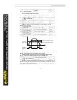
These parameters are used to set the delay time of output terminals FMR, relay 1, relay 2, DO1
and DO2 from status change to actual output.
P5.22
DO valid
mode
selection
One’s place
FMR valid mode
00000
☆
Positive logic
0
Negative logic
1
Ten’s place
RELAY1 valid mode
Positive logic
0
Negative logic
1
Hundred’s place
RELAY2 valid mode
Positive logic
0
Negative logic
1
Thousand's place
DO1 valid mode
Positive logic
0
Negative logic
1
Ten thousand's place
DO2 valid mode
Positive logic
0
Negative logic
1
It is used to set the logic of output terminals FMR, relay 1, relay 2, DO1 and DO2.
•
0: Positive logic
The output terminal is valid when being connected with COM, and invalid when being
disconnected from COM.
•
1: Positive logic
The output terminal is invalid when being connected with COM, and valid when being
disconnected from COM.
Содержание DLB1-0D40S2G
Страница 10: ...10 Graph 1 5 5 5 7 5KW product outline dimensions Graph 1 611 18 5KW product outline dimensions...
Страница 11: ...11 Graph 1 722 30KW product outline dimensions Graph 1 837 55KW product outline dimensions...
Страница 12: ...12 Graph 1 875 110KW product outline dimensions Graph 1 9 132 160KW product outline dimensions...
Страница 14: ...14 2 Wirings 2 1 Standard wiring diagrams Graph 2 8 0 4 18 5KW inverter wiring diagram...
Страница 15: ...15 Graph 2 922 400KW inverter wiring diagram...
Страница 159: ...159...


