-64-
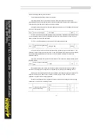
P4.13
AI curve 1 minimum input
0.00V~P4.15
0.00V
☆
P4.14
Corresponding setting of AI
curve 1 minimum input
-100.00%~100.0%
0.0%
☆
P4.15
AI curve 1 maximum input
P4.13~10.00V
10.00V
☆
P4.16
Corresponding setting of AI
curve 1 maximum input
-100.00%~100.0%
100.0%
☆
P4.17
AI1 filter time
0.00s~10.00s
0.10s
☆
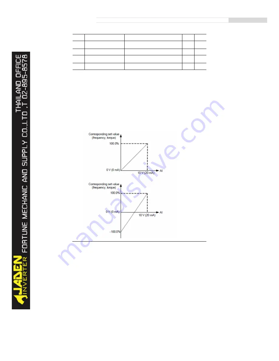
These parameters are used to define the relationship between the analog input voltage and the
corresponding setting. When the analog input voltage exceeds the maximum value (P4.15), the
maximum value is used. W hen the analog input voltage is less than the minimum value (P4.13), the value
set in P4.34 (Setting for AI less than minimum input) is used.
When the analog input is current input, 1 mA current corresponds to 0.5 V voltage.
P4.17 (AI1 filter time) is used to set the software filter time of AI1. If the analog input is liable to
interference, increase the value of this parameter to stabilize the detected analog input. However,
increase of the AI filter time will slow the response of analog detection. Set this parameter properly based
on actual conditions.
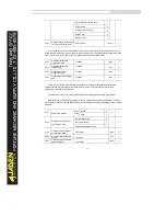
Graph below are two typical setting examples:
Содержание DLB1-0D40S2G
Страница 10: ...10 Graph 1 5 5 5 7 5KW product outline dimensions Graph 1 611 18 5KW product outline dimensions...
Страница 11: ...11 Graph 1 722 30KW product outline dimensions Graph 1 837 55KW product outline dimensions...
Страница 12: ...12 Graph 1 875 110KW product outline dimensions Graph 1 9 132 160KW product outline dimensions...
Страница 14: ...14 2 Wirings 2 1 Standard wiring diagrams Graph 2 8 0 4 18 5KW inverter wiring diagram...
Страница 15: ...15 Graph 2 922 400KW inverter wiring diagram...
Страница 159: ...159...


