-19-
2.3.3Control circuitwiring notes
1.
Analog input terminal
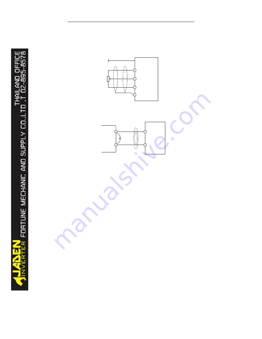
As analogy voltage signals can be easily affected by external interference,
shielded cables shall be used. Cables shall be as short as possible and not exceeding 20
meters. As shown in Graph 2-12 & 2-13, in some severe circumstances, filter
capacitor or ferrite bread shall be used in analog signal side.
PE
+10V
GND
AI
1
DLB1
P
o
te
n
ti
o
m
e
te
r
Les
s
t
han
20m
Graph 2-12Analog input terminal wiring
DLB1
AI
1
GND
0.
022uF
50V
Fer
r
i
t
e
br
ead
Ext
er
nal
anal
og
s
our
ce
Graph 2-13Analog input terminaltreatment
2.
Digital input terminal
Shielded cables shall be used. Cables shall be as short as possible and not
exceeding 20 meters. When using active drive mode, user shall take necessary filter
measures to counter power interference. It is recommended to use node control mode.
Digital inputs include NPN input and PNP input.
(
a
)
NPN input:Most common. Use internal 24V power; +24V terminal
short-circuit with SP terminal; COM terminal is common;J9 is 23 jumper; also known
as drain wiring mode.
Содержание DLB1-0D40S2G
Страница 10: ...10 Graph 1 5 5 5 7 5KW product outline dimensions Graph 1 611 18 5KW product outline dimensions...
Страница 11: ...11 Graph 1 722 30KW product outline dimensions Graph 1 837 55KW product outline dimensions...
Страница 12: ...12 Graph 1 875 110KW product outline dimensions Graph 1 9 132 160KW product outline dimensions...
Страница 14: ...14 2 Wirings 2 1 Standard wiring diagrams Graph 2 8 0 4 18 5KW inverter wiring diagram...
Страница 15: ...15 Graph 2 922 400KW inverter wiring diagram...
Страница 159: ...159...


