-109-
•
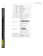
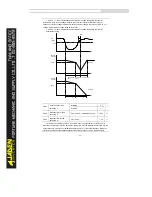
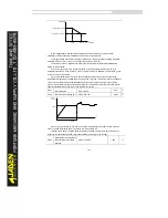
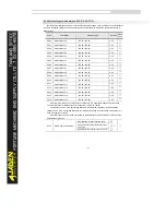
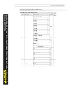
If relative to the maximum frequency (PB.00 = 1), the jump frequency is a fixed value. The
swing frequency is limited by the frequency upper limit and frequency lower limit.
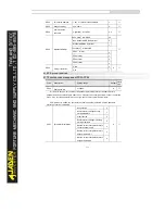
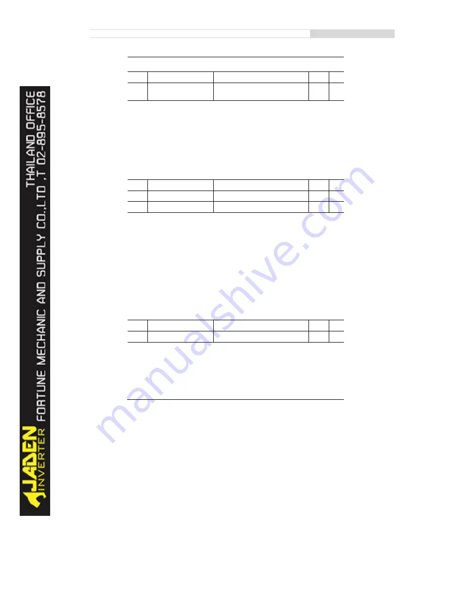
PB.03
Swing frequency cycle
0.0s~3000.0s
10.0s
☆
PB.04
Triangular wave rising time
coefficient
0.0%~100.0%
50.0%
☆
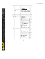
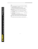
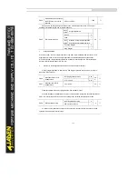
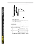
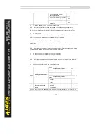
PB.03 specifies the time of a complete swing frequency cycle.
PB.04 specifies the time percentage of triangular wave rising time to PB.03 (Swing frequency
cycle).
•
Triangular wave rising time = PB.03 (Swing frequency cycle) x PB.04 (Triangular wave rising
time coefficient, unit: s)
•
Triangular wave falling time = PB.03 (Swing frequency cycle) x (1 - PB.04 Triangular wave
rising time coefficient ,unit: s)
PB.05
Set length
0m~65535m
1000m
☆
PB.06
Actual length
0m~65535m
0m
☆
PB.07
Number of pulses per meter
0.1~6553.5
100.0
☆
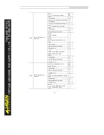
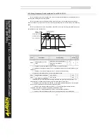
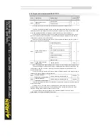
The preceding parameters are used for fixed length control.
The length information is collected by DI terminals. PB.06 (Actual length) is calculated by dividing
the number of pulses collected by the DI terminal by PB.07 (Number of pulses each meter).
When the actual length PB.06 exceeds the set length in PB.05, the DO terminal allocated with
function 10 (Length reached) becomes ON.
During the fixed length control, the length reset operation can be performed via the DI terminal
allocated with function 28. For details, see the descriptions of P4.00 to P4.09.
Allocate corresponding DI terminal with function 27 (Length count input) in applications. If the
pulse frequency is high, DI5 must be used.
PB.08
Set count value
1~65535
1000
☆
PB.09
Designated count value
1~65535
1000
☆
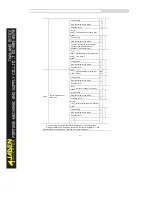
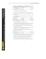
The count value needs to be collected by DI terminal. Allocate the corresponding DI terminal with
function 25 (Counter input) in applications. If the pulse frequency is high, DI5 must be used.
When the count value reaches the set count value (PB.08), the DO terminal allocated with
function 8 (Set count value reached) becomes ON. Then the counter stops counting.
When the counting value reaches the designated counting value (PB.09), the DO terminal
Содержание DLB1-0D40S2G
Страница 10: ...10 Graph 1 5 5 5 7 5KW product outline dimensions Graph 1 611 18 5KW product outline dimensions...
Страница 11: ...11 Graph 1 722 30KW product outline dimensions Graph 1 837 55KW product outline dimensions...
Страница 12: ...12 Graph 1 875 110KW product outline dimensions Graph 1 9 132 160KW product outline dimensions...
Страница 14: ...14 2 Wirings 2 1 Standard wiring diagrams Graph 2 8 0 4 18 5KW inverter wiring diagram...
Страница 15: ...15 Graph 2 922 400KW inverter wiring diagram...
Страница 159: ...159...

