-28-
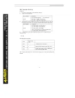
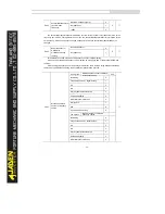
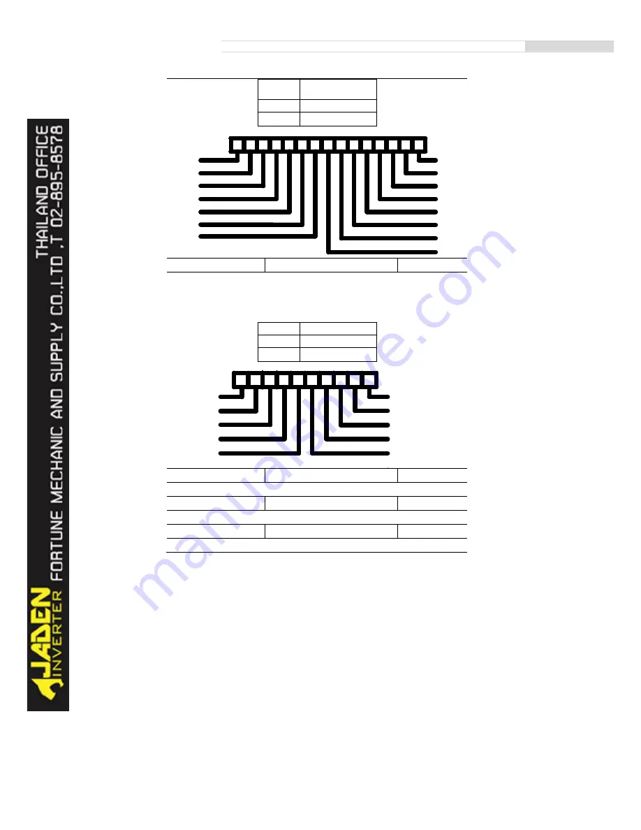
0~14
place
input terminal status
0
invald
1
valid
d0.08
DO output status
1
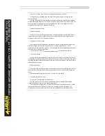
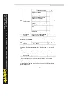
It indicates the current state of DO terminals. After the value is converted into a binary number, each bit
corresponds to a DO. "1" indicates high level signal, and "0" indicates low level signal. The
corresponding relationship between bits and DOs is described in the following table.
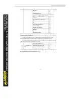
0~9 place
output terminal status
0
invalid
1
valid
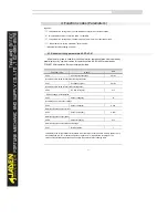
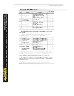
d0.09
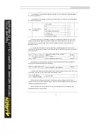
AI1 voltage(V)
0.01V
AI1 input voltage value.
d0.10
AI2 voltage(V)
0.01V
AI2 input voltage value.
d0.11
AI3 voltage(V)
0.01V
AI3 input voltage value.
11
14
13
12
2 11
2
2
2 12
13
14
DI7
DI8
DI10
DI9
7
6
5
4
3
2
1
0
DI1
DI2
10
9
8
DI3
DI4
DI5
DI6
VDI5
VDI4
VDI3
VDI2
VDI1
2
2
2
2
2
2
2
2 0
1
2
3
4
5
6
7
2
2
2 8
9
10
7
6
5
4
3
2
1
0
FMR
TA1-TB1-TC1
9
8
TA2-TB2-TC2
DO1
DO2
VDO1
2
2
2
2
2
2
2
2 0
1
2
3
4
5
6
7
2
2 8
9
VDO2
VDO3
VDO5
VDO4
Содержание DLB1-0D40S2G
Страница 10: ...10 Graph 1 5 5 5 7 5KW product outline dimensions Graph 1 611 18 5KW product outline dimensions...
Страница 11: ...11 Graph 1 722 30KW product outline dimensions Graph 1 837 55KW product outline dimensions...
Страница 12: ...12 Graph 1 875 110KW product outline dimensions Graph 1 9 132 160KW product outline dimensions...
Страница 14: ...14 2 Wirings 2 1 Standard wiring diagrams Graph 2 8 0 4 18 5KW inverter wiring diagram...
Страница 15: ...15 Graph 2 922 400KW inverter wiring diagram...
Страница 159: ...159...


