-56-
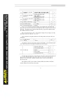
10
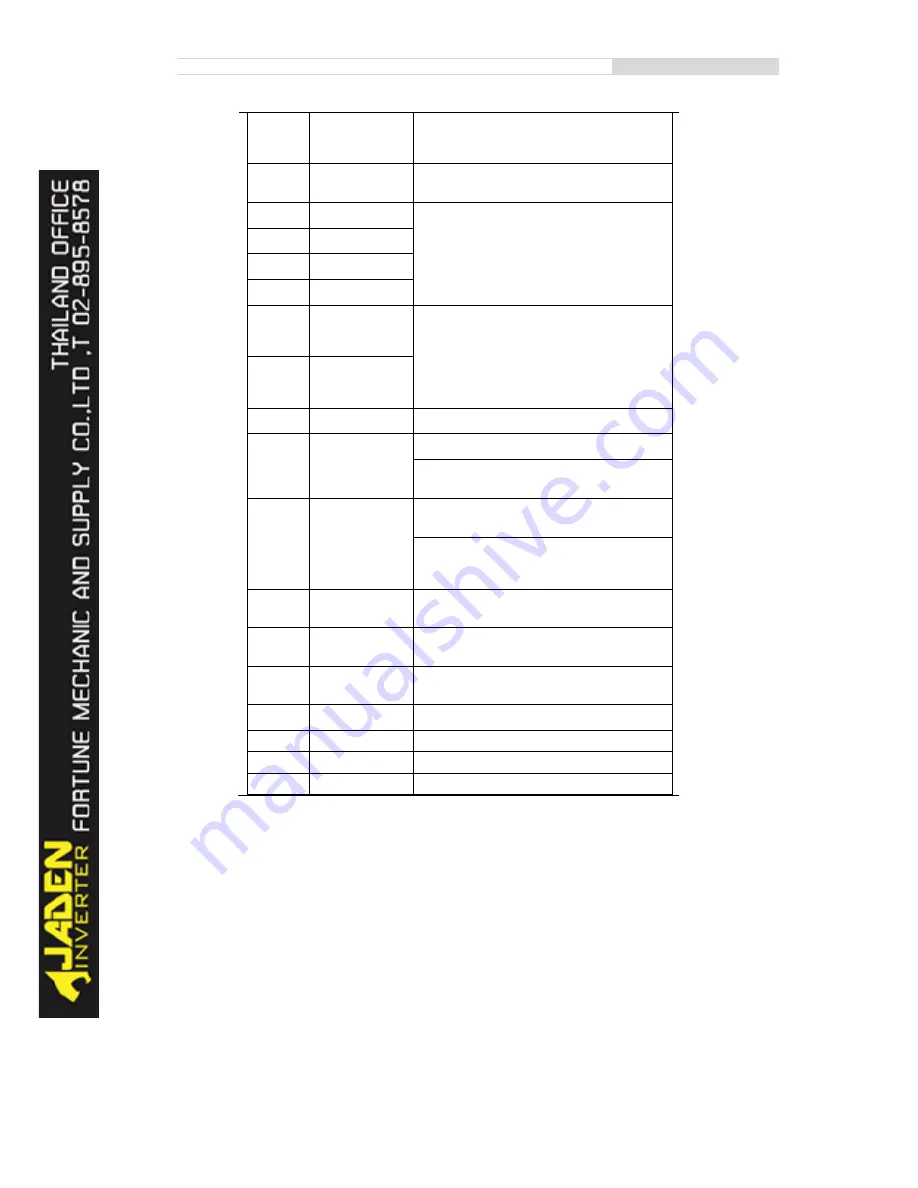
RUN pause
The Inverter decelerates to stop, but the running parameters
are all memorized, such as PLC, swing frequency and PID
parameters. After this function is disabled, the Inverter
resumes its status before stop.
11
Normally open (NO)
input of external fault
If this terminal becomes ON, the Inverter reports 15=E.EIOF
and performs the fault protection action. For more details,
see the description of P9.47.
12
Multi-reference
terminal 1
The setting of 16 speeds or 16 other references can be
implemented through combinations of 16 states of these
four terminals.
13
Multi-reference
terminal 2
14
Multi-reference
terminal 3
15
Multi-reference
terminal 4
16
Terminal 1 for
acceleration/
deceleration time
selection
Totally four groups of acceleration/deceleration time can be
selected through combinations of two states of these two
terminals.
17
Terminal 2 for
acceleration/
deceleration time
selection
18
Frequency source
switchover
The terminal is used to perform switchover between two
frequency sources according to the setting in P0.07.
19
UP and DOW N
setting clear
(terminal, operation
panel)
If the frequency source is digital setting, the terminal is used
to clear the modification by using the UP/
DOW N function or the increment/decrement key on the
operation panel, returning the set frequency to the value of
P0.08.
20
Command source
switchover terminal
If the command source is set to terminal control (P0.02 = 1),
this terminal is used to perform switchover between terminal
control and operation panel control.
If the command source is set to communication control
(P0.02 = 2), this terminal is used to perform switchover
between communication control and operation panel control.
21
Acce le ratio n/Dece
leratio n prohibited
It enables the Inverter to maintain the current frequency
output without being affected by external signals (except the
STOP command).
22
PID pause
PID is invalid temporarily. The Inverter maintains the current
frequency output without supporting PID adjustment of
frequency source.
23
PLC status reset
The terminal is used to restore the original status of PLC
control for the Inverter when PLC control is started again
after a pause.
24
Swing pause
The Inverter outputs the central frequency, and the swing
frequency function pauses.
25
Counter input
This terminal is used to count pulses.
26
Counter reset
This terminal is used to clear the counter status.
27
Length count input
This terminal is used to count the length.
Содержание DLB1-0D40S2G
Страница 10: ...10 Graph 1 5 5 5 7 5KW product outline dimensions Graph 1 611 18 5KW product outline dimensions...
Страница 11: ...11 Graph 1 722 30KW product outline dimensions Graph 1 837 55KW product outline dimensions...
Страница 12: ...12 Graph 1 875 110KW product outline dimensions Graph 1 9 132 160KW product outline dimensions...
Страница 14: ...14 2 Wirings 2 1 Standard wiring diagrams Graph 2 8 0 4 18 5KW inverter wiring diagram...
Страница 15: ...15 Graph 2 922 400KW inverter wiring diagram...
Страница 159: ...159...

