-32-
Commands are given by means of multi-functional input terminals with functions such as FWD, REV,
FJOG, and RJOG.
2: Communication control ("LOCAL" indicator blinking)
Commands are given from upper controllers. If this parameter is set to 2, a communication card (Modbus
RTU, PROFIBUS-DP card, CANlink card, user programmable card or CANopen card) must be installed.
Can refer to PD group function codes for communications.
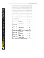
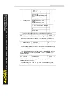
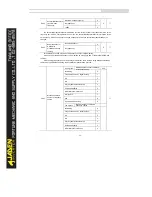
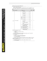
P0.03
Main frequency
source X selection
Keyboard setting frequency(P0.08,
UP/DOW N editable, not retentive at
power failure)
0
0
★
Keyboard setting frequency(P0.08,
UP/DOW N editable, retentive at power
failure)
1
Analog AI1 setting
2
Analog AI2 setting
3
AI3(keyboard potentiometer)
4
High speed pulse setting(DI5)
5
Multi-speed operation setting
6
Simple PLC setting
7
PID control setting
8
Remote communication setting
9
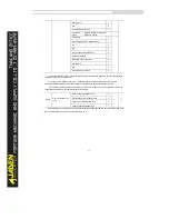
It is used to select the setting channel of the main frequency X. You can set the main frequency in the
following 10 channels:
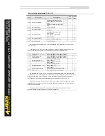
0: Keyboard setting frequency(P0.08, UP/DOWN editable, not retentive at power failure)
The initial value of the set frequency is the value of P0.08 (Preset frequency). You can change the
set frequency by pressing and on the operation panel (or using the UP/DOW N function of input
terminals).
When the Inverter is powered on again after power failure, the set frequency reverts to the value of
P0.08.
1: Keyboard setting frequency(P0.08, UP/DOWN editable, retentive at power failure)
The initial value of the set frequency is the value of P0.08 (Preset frequency). You can change the
set frequency by pressing keys and on the operation panel (or using the UP/DOW N function of input
terminals).
When the Inverter is powered on again after power failure, the set frequency is the value memorized
at the moment of the last power failure.
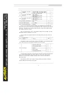
Note that P0.10 determines whether the set frequency is memorized or cleared when the Inverter
stops. It is related to stop rather than power failure.
2:AI1 (0-10 V voltage input or 4-20 mA current input, determined by jumper J8)
Содержание DLB1-0D40S2G
Страница 10: ...10 Graph 1 5 5 5 7 5KW product outline dimensions Graph 1 611 18 5KW product outline dimensions...
Страница 11: ...11 Graph 1 722 30KW product outline dimensions Graph 1 837 55KW product outline dimensions...
Страница 12: ...12 Graph 1 875 110KW product outline dimensions Graph 1 9 132 160KW product outline dimensions...
Страница 14: ...14 2 Wirings 2 1 Standard wiring diagrams Graph 2 8 0 4 18 5KW inverter wiring diagram...
Страница 15: ...15 Graph 2 922 400KW inverter wiring diagram...
Страница 159: ...159...


