-57-
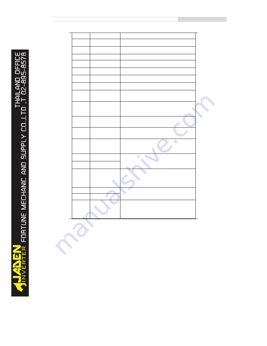
28
Length reset
This terminal is used to clear the length.
29
Torque control
prohibited
The Inverter is prohibited from torque control and enters the
speed control mode.
30
Pulse input (enabled
only for DI5)
DI5 is used for pulse input.
31
Reserved
Reserved.
32
Immediate DC
braking
After this terminal becomes ON, the Inverter directly
switches over to the DC braking state.
33
Normally closed (NC)
input of external fault
After this terminal becomes ON, the
Inverterreports15=E.EIOF and stops.
34
Frequency
modification
forbidden
After this terminal becomes ON, the Inverter does not
respond to any frequency modification.
35
Reverse PID action
direction
After this terminal becomes ON, the PID action direction is
reversed to the direction set in PA.03.
36
External STOP
terminal 1
In operation panel mode, this terminal can be used to stop
the Inverter, equivalent to the function of the STOP key on
the operation panel.
37
Command source
switchover terminal 2
It is used to perform switchover between terminal control
and communication control. If the command source is
terminal control, the system will switch over to
communication control after this terminal becomes ON.
38
PID integral pause
After this terminal becomes ON, the integral adjustment
function pauses. However, the proportional and
differentiation adjustment functions are still valid.
39
Switchover between
main frequency
source X and preset
frequency
After this terminal becomes ON, the frequency source X is
replaced by the preset frequency set in P0.08.
40
Switchover between
auxiliary frequency
source Y and preset
frequency
After this terminal is enabled, the frequency source Y is
replaced by the preset frequency set in P0.08.
41
Reserved
Reserved
42
Reserved
43
PID parameter
switchover
If the PID parameters switchover performed by means of DI
terminal (PA.18 = 1), the PID parameters are PA.05 to
PA.07 when the terminal becomes OFF; the PID parameters
are PA.15 to PA.17 when this terminal becomes ON.
44
User-defined fault 1
If these two terminals become ON, the Inverter reports
27=E.USt1 and 28=E.USt2 respectively, and performs fault
protection actions based on the setting in P9.49.
45
User-defined fault 2
46
Speed control/Torque
control switchover
This terminal enables the Inverter to switch over between
speed control and torque control. When this terminal
becomes OFF, the Inverter runs in the mode set in b0.00.
When this terminal becomes ON, the Inverter switches over
to the other control mode.
Содержание DLB1-0D40S2G
Страница 10: ...10 Graph 1 5 5 5 7 5KW product outline dimensions Graph 1 611 18 5KW product outline dimensions...
Страница 11: ...11 Graph 1 722 30KW product outline dimensions Graph 1 837 55KW product outline dimensions...
Страница 12: ...12 Graph 1 875 110KW product outline dimensions Graph 1 9 132 160KW product outline dimensions...
Страница 14: ...14 2 Wirings 2 1 Standard wiring diagrams Graph 2 8 0 4 18 5KW inverter wiring diagram...
Страница 15: ...15 Graph 2 922 400KW inverter wiring diagram...
Страница 159: ...159...


