-51-
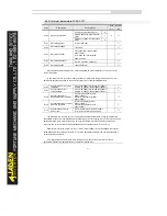
4.5 Vector control parameters:P3.00-P3.22
P3 group is valid for vector control, and invalid for V/F control.
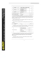
Code
Description
Setting range
Default
Restri
ctions
P3.00
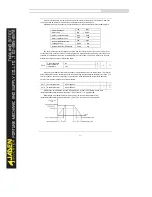
Speed loop proportional gain
1
1~100
30
☆
P3.01
Speed loop integral time 1
0.01s~10.00s
0.50s
☆
P3.02
Switchover frequency 1
0.00~P3.05
5.00Hz
☆
P3.03
Speed loop proportional gain
2
0~100
20
☆
P3.04
Speed loop integral time 2
0.01s~10.00s
1.00s
☆
P3.05
Switchover frequency 2
P3.02~ maximum output frequency
10.00Hz
☆
Speed loop PI parameters vary with running frequencies of the Inverter.
•
If the running frequency is less than or equal to "Switchover frequency 1" (P3.02), the speed loop
PI parameters are P3.00 and P3.01.
•
If the running frequency is equal to or greater than "Switchover frequency 2" (P3.05), the speed
loop PI parameters are P3.03 and P3.04.
•
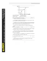
If the running frequency is between P3.02 and P3.05, the speed loop PI parameters are obtained
from the linear switchover between the two groups of PI parameters, as shown in Figure below.
PI
Frequency
P3.00
P3.01
P3.03
P3.04
P3.02
P3.05
Graph 4-5 PI parameters
The speed dynamic response characteristics in vector control can be adjusted by setting the
proportional gain and integral time of the speed regulator.
To achieve a faster system response, increase the proportional gain and reduce the integral time. Be
Содержание DLB1-0D40S2G
Страница 10: ...10 Graph 1 5 5 5 7 5KW product outline dimensions Graph 1 611 18 5KW product outline dimensions...
Страница 11: ...11 Graph 1 722 30KW product outline dimensions Graph 1 837 55KW product outline dimensions...
Страница 12: ...12 Graph 1 875 110KW product outline dimensions Graph 1 9 132 160KW product outline dimensions...
Страница 14: ...14 2 Wirings 2 1 Standard wiring diagrams Graph 2 8 0 4 18 5KW inverter wiring diagram...
Страница 15: ...15 Graph 2 922 400KW inverter wiring diagram...
Страница 159: ...159...

