-100-
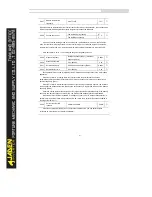
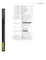
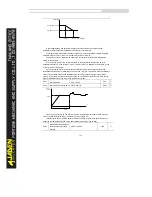
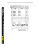
If "Continue to run" is selected, the Inverter continues to run and displays A.****. Therunning
frequency is set in P9.54.
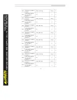
P9.54
Frequency selection for
continuing to run upon fault
Current running frequency
0
0
☆
Set frequency
1
Frequency upper limit
2
Frequency lower limit
3
Backup frequency upon abnormality
4
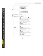
P9.55
Backup frequency upon
abnormality
60.0%~100.0%
100.0
%
☆
If a fault occurs during the running of the Inverter and the handling of fault is set to
"Continue to run", the Inverter displays A.** and continues to run at the frequency set in P9.54.
The setting of P9.55 is a percentage relative to the maximum frequency..
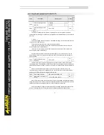
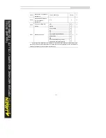
P9.56
Type of motor temperature
sensor
No temperature sensor
0
0
☆
PT100
1
PT1000
2
P9.57
Motor overheat protection
threshold
0
℃
~200
℃
110
℃
☆
P9.58
Motor overheat warning
threshold
0
℃
~200
℃
90
℃
☆
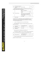
The signal of the motor temperature sensor needs to be connected to the optional I/O
extension card. AI3x on the extension card can be used for the temperature signal input. The
motor temperature sensor is connected to AI3 and PGND of the extension card. The AI3 terminal
of the DLB1 supports both PT100 and PT1000. Set the sensor type correctly during the use. You
can view the motor temperature via d0.34.
If the motor temperature exceeds the value set in P9.57, the Inverter reports an alarm and
acts according to the selected fault protection action.
If the motor temperature exceeds the value set in P9.58, the DO terminal on the Inverter
allocated with function 39 (Motor overheat warning) becomes ON.
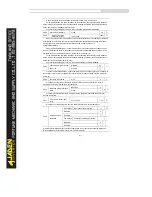
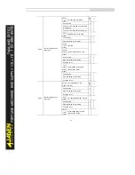
P9.59
Action selection at
instantaneous power failure
Invalid
0
0
☆
Decelerate
1
Decelerate to stop
2
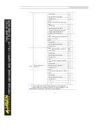
P9.60
Action pause judging voltage
at instantaneous power
failure
80.0%~100.0%
90.0%
☆
P9.61
Voltage rally judging time at
instantaneous power failure
0.00s~100.00s
0.50s
☆
P9.62
Action judging voltage at
instantaneous power failure
60.0%~100.0%(standard bus voltage)
80.0%
☆
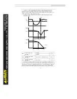
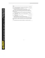
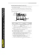
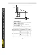
Upon instantaneous power failure or sudden voltage dip, the DC bus voltage of the Inverter
reduces. This function enables the Inverter to compensate the DC bus voltage reduction with the
load feedback energy by reducing the output frequency so as to keep the Inverter running
continuously.
Содержание DLB1-0D40S2G
Страница 10: ...10 Graph 1 5 5 5 7 5KW product outline dimensions Graph 1 611 18 5KW product outline dimensions...
Страница 11: ...11 Graph 1 722 30KW product outline dimensions Graph 1 837 55KW product outline dimensions...
Страница 12: ...12 Graph 1 875 110KW product outline dimensions Graph 1 9 132 160KW product outline dimensions...
Страница 14: ...14 2 Wirings 2 1 Standard wiring diagrams Graph 2 8 0 4 18 5KW inverter wiring diagram...
Страница 15: ...15 Graph 2 922 400KW inverter wiring diagram...
Страница 159: ...159...


