-149-
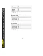
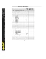
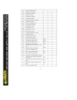
P8.42
Timing function
0
P8.43
Timing duration source
0
P8.44
Timing duration
0.0Min
P8.45
AI1 input voltage lower limit
3.10V
P8.46
AI1 input voltage upper limit
6.80V
P8.47
Module temperature threshold
75
℃
P8.48
Cooling fan control
0
P8.49
Wakeup frequency
0.00Hz
P8.50
Wakeup delay time
0.0s
P8.51
Dormant frequency
0.00Hz
P8.52
Dormant delay time
0.0s
P8.53
Current running time reached
0.0Min
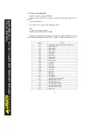
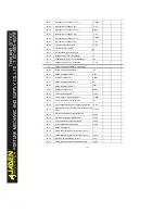
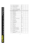
P9
Fault and protection: P9.00-P9.70
P9.00
Motor overload protection selection
1
P9.01
Motor overload protection gain
1.00
P9.02
Motor overload warning coefficient
80%
P9.03
Over-voltage stall gain
0
P9.04
Over-voltage stall protective voltage
130%
P9.05
Over-current stall gain
20
P9.06
Over-current stall protective current
150%
P9.07
Short-circuit to ground upon power- on
1
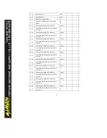
P9.09
Fault auto reset times
0
P9.10
DO action during fault auto reset
0
P9.11
Time interval of fault auto reset
1.0s
P9.12
Input phase loss protection
11
P9.13
Output phase loss protection selection
1
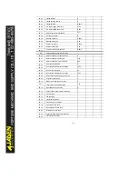
P9.14
1st fault type
-
P9.15
2nd fault type
-
P9.16
3rd (latest) fault type
-
P9.17
Frequency upon 3rd fault
-
P9.18
Current upon 3rd fault
-
P9.19
Bus voltage upon 3rd fault
-
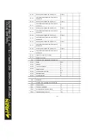
P9.20
DI status upon 3rd fault
-
P9.21
Output terminal status upon 3rd fault
-
P9.22
3rd faultinverter status
-
Содержание DLB1-0D40S2G
Страница 10: ...10 Graph 1 5 5 5 7 5KW product outline dimensions Graph 1 611 18 5KW product outline dimensions...
Страница 11: ...11 Graph 1 722 30KW product outline dimensions Graph 1 837 55KW product outline dimensions...
Страница 12: ...12 Graph 1 875 110KW product outline dimensions Graph 1 9 132 160KW product outline dimensions...
Страница 14: ...14 2 Wirings 2 1 Standard wiring diagrams Graph 2 8 0 4 18 5KW inverter wiring diagram...
Страница 15: ...15 Graph 2 922 400KW inverter wiring diagram...
Страница 159: ...159...

