-85-
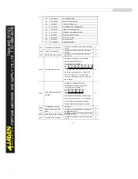
P8.19
Frequency detection value
(FDT1)
0.00Hz~ maximum frequency
50.00Hz
☆
P8.20
Frequency detection hysteresis
(FDT hysteresis 1)
0.0%~100.0%(FDT1
电平
)
5.0%
☆
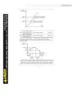
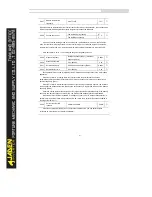
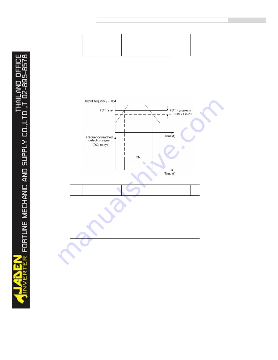
If the running frequency is higher than the value of P8.19, the corresponding DO terminal
becomes ON. If the running frequency is lower than value of P8.19, the DO terminal goes OFF
These two parameters are respectively used to set the detection value of output frequency and
hysteresis value upon cancellation of the output. The value of P8.20 is a percentage of the hysteresis
frequency to the frequency detection value (P8.19).
The FDT function is shown in the following figure.
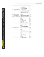
P8.21
Detection range of
frequency reached
0.00%~100%( maximum frequency)
0.0%
☆
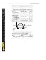
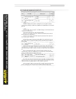
If the Inverter running frequency is within the certain range of the set frequency, the corresponding
DO terminal becomes ON.
This parameter is used to set the range within which the output frequency is detected to reach the
set frequency. The value of this parameter is a percentage relative to the maximum frequency. The
detection range of frequency reached is shown in the following figure.
Содержание DLB1-0D40S2G
Страница 10: ...10 Graph 1 5 5 5 7 5KW product outline dimensions Graph 1 611 18 5KW product outline dimensions...
Страница 11: ...11 Graph 1 722 30KW product outline dimensions Graph 1 837 55KW product outline dimensions...
Страница 12: ...12 Graph 1 875 110KW product outline dimensions Graph 1 9 132 160KW product outline dimensions...
Страница 14: ...14 2 Wirings 2 1 Standard wiring diagrams Graph 2 8 0 4 18 5KW inverter wiring diagram...
Страница 15: ...15 Graph 2 922 400KW inverter wiring diagram...
Страница 159: ...159...


