-84-
It is used to set the Inverter running mode when the set frequency is lower than the frequency
lower limit. The DLB1 provides three running modes to satisfy requirements of various applications.
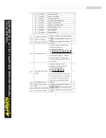
P8.15
Droop control
0.00Hz~10.00Hz
0.00Hz
☆
This function is used for balancing the workload allocation when multiple motors are used to drive
the same load.
The output frequency of the Inverters decreases as the load increases. You can reduce the
workload of the motor under load by decreasing the output frequency for this motor, implementing
workload balancing between multiple motors.
P8.16
Accumulative power-on time
threshold
0h~65000h
0h
☆
If the accumulative power-on time (P7.13) reaches the value set in this parameter, the
corresponding DO terminal becomes ON.
For example, combining DI/DO functions, to implement the function that the Inverter reports an
alarm when the actual accumulative power-on time reaches the threshold of 100 hours, perform the
setting as follows:
1) Set DI1 to user-defined fault 1: P4.00 = 44.
3) Set DO1 to power-on time reached: P5.04 = 24.
4) Set the accumulative power-on time threshold to 100 h: P8.16 = 100h.
Then, the Inverter reports 26=E.ArA when the accumulative power-on time reaches 100 hours.
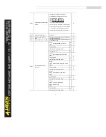
P8.17
Accumulative running time
threshold
0h~65000h
0h
☆
It is used to set the accumulative running time threshold of the Inverter. If the accumulative
running time (P7.09) reaches the value set in this parameter, the corresponding DO terminal becomes
ON.
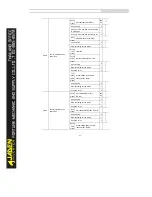
P8.18
Startup protection
No
0
0
☆
Yes
1
This parameter is used to set whether to enable the safety protection. If it is set to 1, the Inverter
does not respond to the run command valid upon Inverter power-on (for example, an input terminal is
ON before power-on). The Inverter responds only after the run command is cancelled and becomes
valid again.
In addition, the Inverter does not respond to the run command valid upon fault reset of the
Inverter. The run protection can be disabled only after the run command is cancelled.
In this way, the motor can be protected from responding to run commands upon power-on or fault
reset in unexpected conditions.
Содержание DLB1-0D40S2G
Страница 10: ...10 Graph 1 5 5 5 7 5KW product outline dimensions Graph 1 611 18 5KW product outline dimensions...
Страница 11: ...11 Graph 1 722 30KW product outline dimensions Graph 1 837 55KW product outline dimensions...
Страница 12: ...12 Graph 1 875 110KW product outline dimensions Graph 1 9 132 160KW product outline dimensions...
Страница 14: ...14 2 Wirings 2 1 Standard wiring diagrams Graph 2 8 0 4 18 5KW inverter wiring diagram...
Страница 15: ...15 Graph 2 922 400KW inverter wiring diagram...
Страница 159: ...159...


