-139-
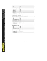
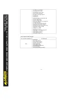
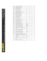
BIT2:RELAY1 output control
BIT3:RELAY2 output control
BIT4:FMR output control
BIT5:VDO1
BIT6:VDO2
BIT7:VDO3
BIT8:VDO4
BIT9:VDO5
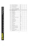
Analog outputAO1 control:(write only)
Command address
Command content
2002
0~7FFF for 0
%
~100
%
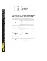
Analog outputAO2 control:(write only)
Command address
Command content
2003
0~7FFF for 0
%
~100
%
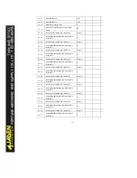
Pulse output control:(write only)
Command address
Command content
2004
0~7FFF for 0
%
~100
%
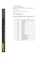
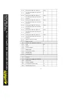
Inverter fault description:
Inverter fault address
Inverter fault information
8000
0000:No fault
0001:reserved
0002:Over-current during acceleration
0003:Over-current during deceleration
0004:Over-current at constant speed
0005:Over-voltage during acceleration
0006:Over-voltage during deceleration
0007:Over-voltage at constant speed
0008:Control power suplly fault
0009:Under-voltage
000A:Inverter over-load
000B:Motor overload
000C:Power input phase loss
000D:Power output phase loss
000E:Module over-heat
000F:External equipment fault
0010:Communication fault
0011:Contactor fault
0012:Current detection fault
Содержание DLB1-0D40S2G
Страница 10: ...10 Graph 1 5 5 5 7 5KW product outline dimensions Graph 1 611 18 5KW product outline dimensions...
Страница 11: ...11 Graph 1 722 30KW product outline dimensions Graph 1 837 55KW product outline dimensions...
Страница 12: ...12 Graph 1 875 110KW product outline dimensions Graph 1 9 132 160KW product outline dimensions...
Страница 14: ...14 2 Wirings 2 1 Standard wiring diagrams Graph 2 8 0 4 18 5KW inverter wiring diagram...
Страница 15: ...15 Graph 2 922 400KW inverter wiring diagram...
Страница 159: ...159...

