ORBIMAT CA
| Operating instructions
Service and troubleshooting
(09.03.15) OW_ORBIMAT_CA_BA_871060202_04_EN
orbitalum tools
GmbH, D-78224 Singen, www.orbitalum.com, Tel. +49 (0) 77 31 792-0
73
45
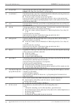
Incorrect weld head
connected!
The currently connected weld head is not the same as the weld head in the started
procedure.
X
Select connected weld head in the procedure.
– or –
X
Connect the weld head selected in the procedure to the machine.
Are the weld head models identical, but the message appears anyway?
X
Contact Orbitalum service.
46
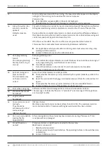
The procedure contains
parameters which lie
outside the limit values
for the selected weld
head!
Weld head changed in procedure. Weld head does not match the one in the parameters.
The weld head list of the machine contains the parameters of the weld heads which
can be connected to the machine, e.g. the maximum rotation of the rotor, the maximum
pipe diameter to be welded and the maximum permissible current.
X
Adjust parameters of the program to the selected weld head.
9.4
Status LED indicators
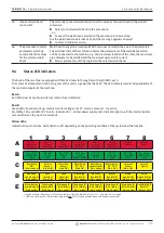
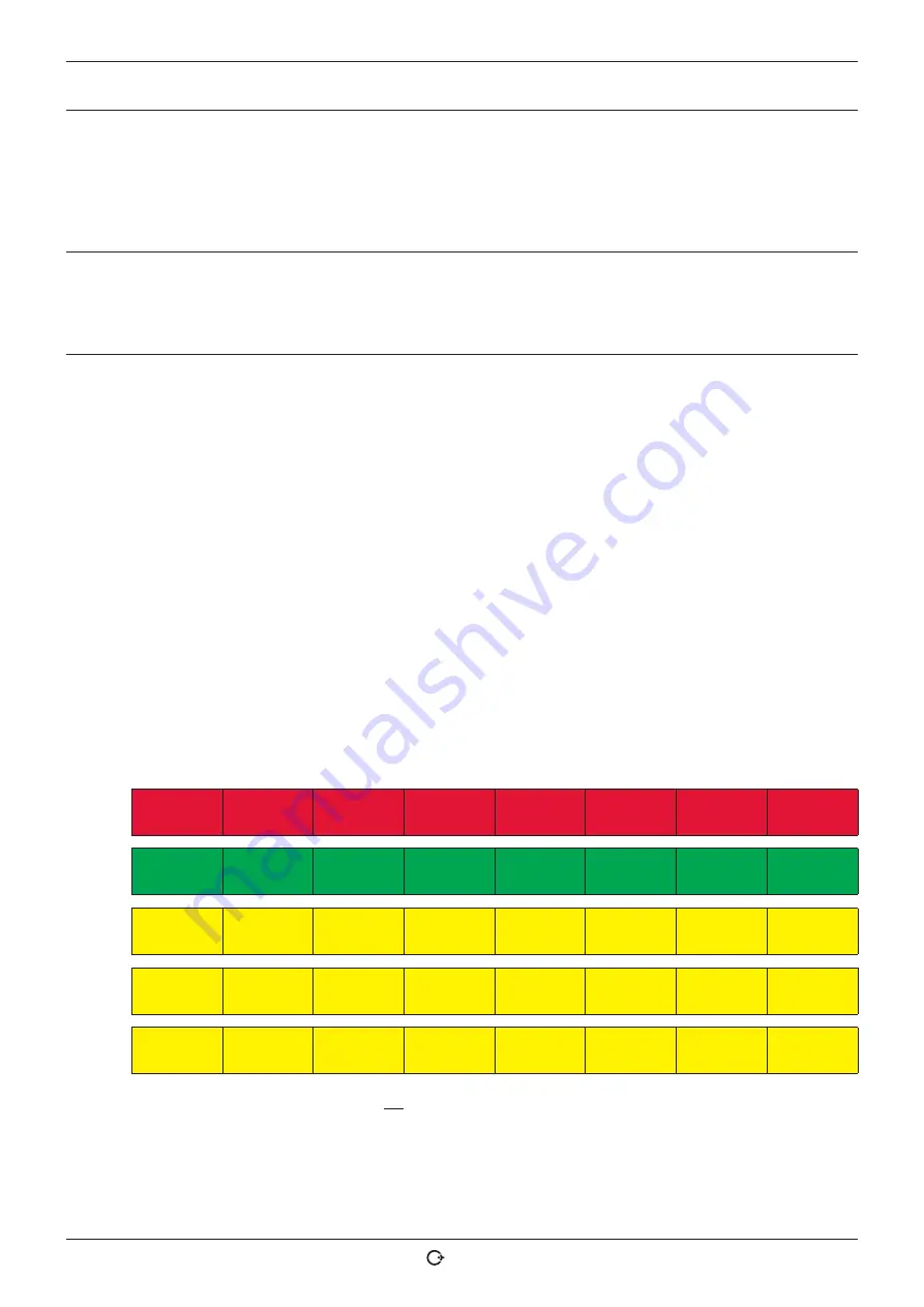
The back of the machine is equipped with five LED rows (A through E) with eight LEDs each.
The status of all important internal signals of the unit is signaled by the LEDs. The LED indicators work independently of
the control computer of the machine.
Row A:
Red LEDs (row A) are lit up: Internal control fuses defective.
Row B:
Green LEDs (row B) are lit up: Internal control voltages for PC, motor, valves etc. are active.
For OM 165 CA and OM 300 CA units: Indicator B2 – printer power supply unit. Indicator lights up if the internal printer
was switched on (by a print command).
Yellow LEDs:
Indicate various functions. Switched on or off depending on the operating condition of the system and the function.
1
2
3
4
5
6
7
8
A
Fuse 1
Weld head
(defective)
Fuse 2
Printer
(defective)
Fuse 3
Motor
(defective)
Fuse 4
Pump, PU1
(defective)
Fuse 5
Computer
(defective)
Fuse 6
Pump, PU2
(defective)
not used
(spare)
not used
(spare)
B
PS – WH
Weld head
(OK)
PS – PR
Printer
(OK)
PS – MOT
Motor
(OK)
not used
(spare)
(jump. to B3)
PS – PC
Computer
(OK)
24 _DI
int. supply
(OK)
PS – INV
int. supply
(OK)
U – sense
(LED A row)
(OK)
C
Keyswitch
ON
(= full menue)
Arc Gas
Sensor
(ON = OK)
Water Flow
Sensor*
(ON = OK)
Water Pump
PS - PU 1
(ON = OK)
Water Pump
enable signal
(ON = enabl.)
Water Pump
PS - PU 2
(ON = OK)
external
Sensor
(ON = OK)
not used
(spare)
D
Fas Valve
enable signal
(ON = enabl.)
Fan 1
(left side)
(ON = OK)
Fan 2
(right side)
(ON = OK)
Start Stop
Key (WH-T)
(ON = enabl.)
Gas Test
Key (WH-E)
(ON = enabl.)
Motor
Key (WH-S)
(ON = enabl.)
Home
Key (WH-D)
(ON = enabl.)
Home
Switch (WH-A)
(ON = enabl.)
E
Motor Releay
enable signal
(ON = enabl.)
Twin Switch
Signal (WH-F)
(ON = Pos.2)
Weld head ID
Bit 0 (WH-L)
(ON = enabl.)
Weld head ID
Bit 1 (WH-M)
(ON = enabl.)
Weld head ID
Bit 2 (WH-N)
(ON = enabl.)
Weld head ID
Bit 3 (WH-U)
(ON = enabl.)
Weld head ID
Bit 4 (WH-W)
(ON = enabl.)
CAJON-MODE
(WH-G)**
(ON = enabl.)
* signals for Water Flow Sensor (C3) not available on OM 165 CB with S/N 102 to 111 - only over service screen.
** LED only ON, when CAJON interface integrated
and
CAJON mode enabled (head with adaptor connected).

