Positioning module UVE8112, IMD10 DcSetup
programme
If the motor is connected correctly, it should rotate to the right in case of a positive direction and to
the left in case of a negative direction (viewed from the front).
Here, the rotation direction of the motor can be adapted so that it corresponds to the defined axis
direction of the connected mechanical facilities. For this purpose, a dialogue box can be displayed by
means of which the axis is moved into the positive or negative direction.
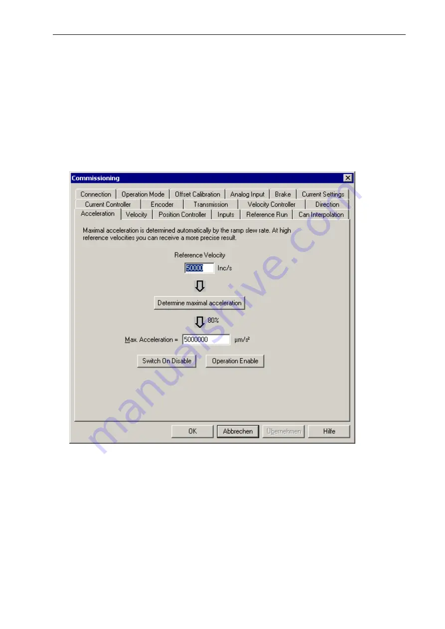
Acceleration dialogue box
If the analogue mode of operation (current or velocity controller) is activated, the default axis direction
has to be chosen. Otherwise, the movement of the motor during the switch-on is uncontrolled.
Note:
If the axis direction is changed, the limit switch inputs of the positive and negative limit switch
are also inverted.
he maximum acceleration is the limitation for the acceleration of all motion functions with a ramp
otor back and forth. At the same time, the build-up
T
(profile velocity mode, profile position mode). I.e. the acceleration cannot become greater than this
value, even if a different parameter (e.g. profile acceleration) contains a higher value.
The determination of the maximum acceleration can be carried out automatically. For this, a
rectangular signal is used in order move the m
times of the ramps are measured and averaged. This value is limited to 80 % in order to have a
certain reserve for the control.
It has to be taken into account that the calculation becomes very imprecise in case of relatively small
speeds. The target speed should come to about ¼ of the maximum speed or more.
57
Содержание IMD1
Страница 1: ...DC servo positioning module with CanOpen interface UVE8112 IMD10 www isel com ...
Страница 66: ...DcSetup programme Positioning module UVE8112 IMD10 66 ...
Страница 113: ...Positioning module UVE8112 IMD10 Appendix 113 Appendix UVE8112 package dimensions ...
Страница 114: ...Appendix Positioning module UVE8112 IMD10 114 IMD10 package dimensions ...


