DcSetup programme
Positioning module UVE8112, IMD10
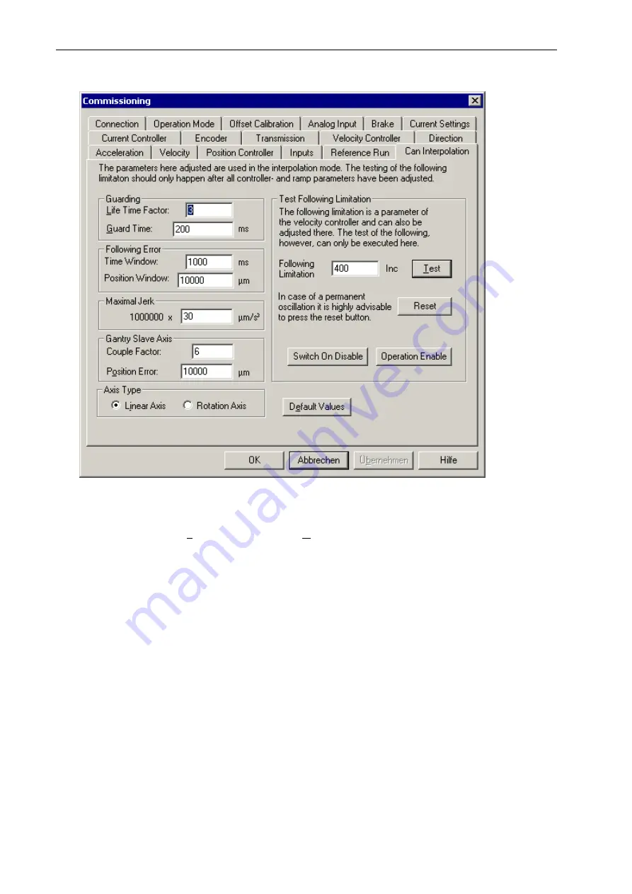
Can Interpolation dialogue box
The parameters set here were designed for the modes of operation “Position controller with ramp
profile” and “Position controller for interpolation” (see “Operation Mode dialogue box” on page 44).
The two parameters “Life Time Factor“ and “Guard Time“ can be used to activate the watchdog
function of the positioning module (see Monitoring – Guarding on page 76). If the value of one the
two parameters equals 0, the watchdog function is switched off.
The monitoring of the following error is carried out by means of the two parameters “Time window”
and “Position window”. If the actual position for the “Time window” time deviates from the target value
by the “Position window” amount, an internal flag is set. A superordinate control can query this flag
and react accordingly.
The axis’ vibration behaviour can be influenced by the “Maximum jerk” parameter. The smaller the
jerk value, the less the vibration of the axis during the accelerating and braking processes. In return,
the acceleration and braking process takes longer accordingly. The jerk value can be read in and
used by the CNC control. Within the final power stage, this parameter is not used. The CNC control
of ISEL uses this parameter.
Concerning the axis type, the axis can either be set as a linear or as rotary axis. The CNC control of
ISEL uses this parameter for the display. Otherwise, the axis type is not used.
In case of a gantry axis, where two axes are to be moved synchronously, the maximum position error
can be freely defined. This limit value is monitored only by the slave axis. The master axis does not
take into account this limit value. If the deviation of position between the master axis and the slave
axis exceeds this value, the slave axis is immediately stopped with the error code 22 (see section on
fault states). The related master axis is informed of this error via the CAN bus and stops immediately
with the error code 28.
In case of a gantry axis’ slave axis, the user also has the possibility to define the coupling factor. The
greater the factor, the “closer” the slave axis is connected with the master axis. Thus, the deviation of
62
Содержание IMD1
Страница 1: ...DC servo positioning module with CanOpen interface UVE8112 IMD10 www isel com ...
Страница 66: ...DcSetup programme Positioning module UVE8112 IMD10 66 ...
Страница 113: ...Positioning module UVE8112 IMD10 Appendix 113 Appendix UVE8112 package dimensions ...
Страница 114: ...Appendix Positioning module UVE8112 IMD10 114 IMD10 package dimensions ...


