Description of the drive module
Positioning module UVE8112, IMD10
Wiring of the inputs and outputs
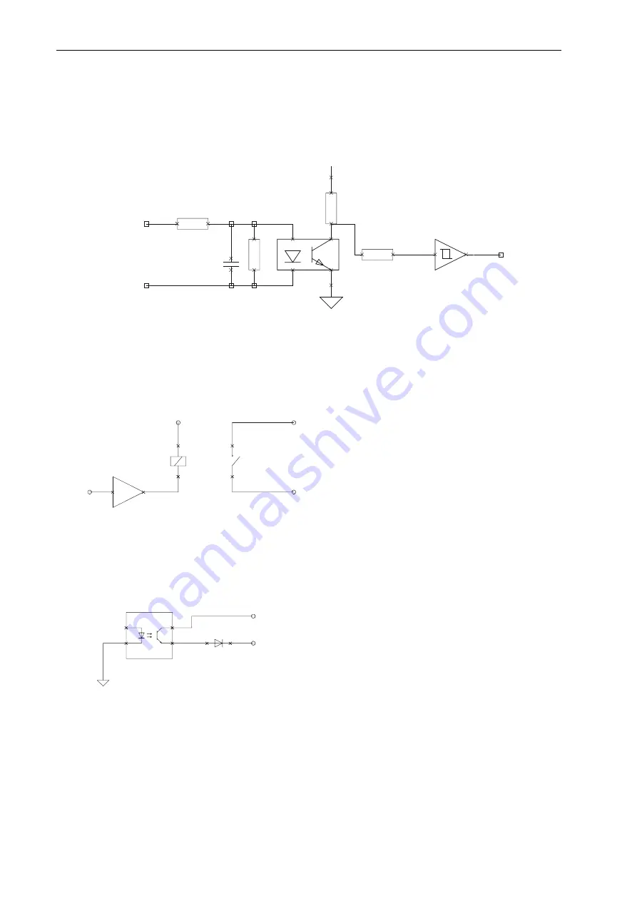
Digital inputs, limit switches, reference switches, Enable
The evaluation of the inputs can be set by means of software.
See “Inputs dialogue box” on page 63.
P2.0
GND 24V
Input
VCC
4K7
1
2
4K
7
10K
2K
2
3
4
TLP124
10NF
5
6
74HCT14SO
Digital Ready output
The Ready output is designed as a potential-free contact. It indicates the operational readiness of
the module and is only set, if the module software works correctly (monitoring through internal
watchdog timer). The design as a potential-free contact makes it possible to easily link several
Ready outputs. This sum signal can be processed e.g. in the safety circuit.
1
2
4
1
2
3
+24V
REL1
REL1
Ready In
Ready Out
Digital Homing output
The Homing output can be used to shunt the limit switch in the safety circuit. It is set during the
reference run (on limit switch).
DGND
1
2
3
4
K
A
1
2
TLP124
+24V
Homing output
Digital Brake output
The Brake output is used for the brake control. The way in which the brake is controlled can be
defined by means of the software.
20
Содержание IMD1
Страница 1: ...DC servo positioning module with CanOpen interface UVE8112 IMD10 www isel com ...
Страница 66: ...DcSetup programme Positioning module UVE8112 IMD10 66 ...
Страница 113: ...Positioning module UVE8112 IMD10 Appendix 113 Appendix UVE8112 package dimensions ...
Страница 114: ...Appendix Positioning module UVE8112 IMD10 114 IMD10 package dimensions ...


