Icom IP1000C Скачать руководство пользователя страница 226

5

MAINTENANCE

5-2

1. How to save the IP1000C’s setting to a PC

You can save the IP1000C’s settings of its setting screen to a PC or USB flash drive.

The saved settings can be used to recover the configuration.


L

The settings can be directly loaded into the IP1000C from the USB flash drive.


Saving the setting

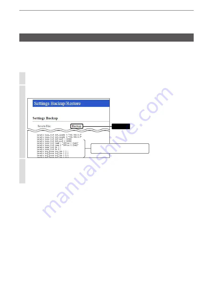
Click [Management], then [Settings Backup/Restore].

 • The [Settings Backup/Restore] screen appears.

Click <Backup>.

 • The File Saving window appears.

The settings that have been changed 

from the factory defaults.

Click

Select a desired folder/location, then click [Save] in the File Saving window.


L

The setting file (extension: “sav”) is saved in the selected folder.


L

The default file name is composed of the model name (IP1000C), version number and date.

Содержание IP1000C

Страница 1: ...MANUAL IP1000C IP ADVANCED RADIO SYSTEM CONTROLLER INTRODUCTION 1 BEFORE USING THE IP1000C 2 SETTING UP THE IP1000C SYSTEM 3 OTHER BASIC FUNCTIONS 4 ABOUT THE SETTING SCREEN 5 MAINTENANCE 6 FOR YOUR...

Страница 2: ...ic or mechanical including photocopying recording or by any information storage and retrieval system without express written permission from Icom Incorporated All stated specifications and design are...

Страница 3: ...imiting to a certain area If you connect with Icom s VE PG3 ver 1 13 or later you will be able to communicate with certain types of Icom transceivers Also If you connect in bridge port with Icom s VE...

Страница 4: ...alue Network Settings IP Address IP Address IP Address 192 168 0 1 Subnet Mask 255 255 255 0 DHCP Server DHCP Server DHCP Server Disable Management Administrator Administrator Username admin fixed Cur...

Страница 5: ...ng screen CONNECTION GUIDE Section 2 Connect to a PC and turn ON the power CONNECTION GUIDE Configuring the network connection pp 4 11 4 12 Registering the terminals pp 2 5 2 6 Configuring the setting...

Страница 6: ...ection 1 5 M MConnecting transceivers 1 6 M MConnecting a telephone and transceivers 1 6 M MSimplex and Full Duplex 1 7 M MMulti communication 1 7 M MAll Call and Group Call 1 8 M MTalkgroup Call 1 9...

Страница 7: ...green 2 After INIT is pushed until the default resets are completed Blinks orange and green alternately 3 MSG Not lit The latest firmware is installed Lights green A firmware update is ready Online up...

Страница 8: ...h drive Insert a USB flash drive purchase separately to recover the configuration or to update the firmware p 5 9 Turn OFF the IP1000C s power before inserting or removing the USB flash drive to preve...

Страница 9: ...a HUB LED indication Lights Blinks q Green w Orange q w LAN connected LAN data communicating 1000BASE T 10BASE T 100BASE TX 3 INIT button If you forget its IP address and you cannot access to the IP10...

Страница 10: ...elp file for more details CS IP100H Cloning software The CS IP100H cloning software is designed to be used for data entry setting and programming for the IP100H from a PC You can download the free sof...

Страница 11: ...Only the VE PG3 s controller ports that are set as the bridge mode are connectable Connecting a telephone and transceivers If you connect in bridge connection with Icom s VE PG3 ver 1 13 or later you...

Страница 12: ...ables Full Duplex Simplex IP100H VOX function 1 Set in the IP1000C Hands free PTT operation HM 153 earphone microphone OPC 2144 HM 153LS earphone microphone HM 166 earphone microphone OPC 2144 HM 166L...

Страница 13: ...to call all the WLAN transceivers and IP100FS that are registered in the Transceiver Registration window in the IP1000C About Group Calls The Group Call function is used to call the desired group sele...

Страница 14: ...n Settings screen is set to Multiplex Talkgroup the WLAN transceivers can make a Talkgroup Call between the linked talkgroups Set to the IP1000C whether All Call includes the Talkgroup or not or the T...

Страница 15: ...he calling mode only the transmitting operation is needed to communicate with the transceiver you are calling Individual Call Sales 1 Calling mode IP1000C Wireless access point IP100H Sales 2 Sales 3...

Страница 16: ...Includes from an IP100FS Group Call High Enable Includes the Area Call or calling from an IP100FS All Call Normal Disable Includes the Area Call Individual Call Normal Disable Low Group Call Normal Di...

Страница 17: ...Example For Sales and For Accounts When the IP100FS uses the Area Call function can call IP100Hs that are in the communication range of the access points assigned to the Area Call Select the access p...

Страница 18: ...on screen TX Received message screen RX IP100FS transmits a message Selected Call type Selected or edited message IP1000C IP100H Wireless access point 1 25 12 57 All Gather imme Blinks Scrolls The IP1...

Страница 19: ...rammed The status information sent using the WLAN transceiver can be displayed in the One Touch Button screen or in the Transceiver Management screen on the Transceiver Settings menu To use this funct...

Страница 20: ...the registration and rebooting the WLAN transceiver 2 6 M MAbout the WLAN transceiver settings 2 7 M MAbout the Group calls 2 8 M MAbout the Talkgroup calls 2 9 M MAbout the ID list 2 10 M MAbout mes...

Страница 21: ...00C into the address bar L L The default IP address is 192 168 0 1 http 192 168 0 1 2 Push the Enter key The Login Authentication screen will appear 3 Enter admin fixed username and admin default pass...

Страница 22: ...nctions to all the WLAN transceivers that are registered on the Transceiver Registration screen Use ID list Communication Method Simplex Full Duplex Priority Call Area Call Message Status 4 Destinatio...

Страница 23: ...ments to register an IP100H to an IP1000C IP1000C IP100H Wireless access point IP100FS Remote communicator 192 168 0 1 192 168 0 50 Sales1 00001 Sales2 00002 Sales3 00003 Sales4 00004 Sales group1 001...

Страница 24: ...displayed 1 Enter the Transceiver Model Name and Unit ID items in the Transceiver Settings field and then click Add 2 After registration is finished confirm the registered contents the terminal in the...

Страница 25: ...mmunication terminal is not registered or not connected to the IP1000C About updating setup If the IP1000C s setup has been changed be sure to reboot the IP100H to read its setting 2 Transceiver setti...

Страница 26: ...been changed the WLAN transceiver needs to be rebooted After registration is finished confirm the registered contents in the Transceiver Setting List field 4 Click Transceiver Settings then Transceive...

Страница 27: ...ngs have been changed the WLAN transceiver needs to be rebooted Click Destination Settings The Destination Settings screen is displayed 1 Enter the group name Call type and Group ID 00001 60000 in the...

Страница 28: ...C The FUNC key or ID List key can be assigned for selecting the Talkgroup After the settings have been changed the WLAN transceiver needs to be rebooted Click Destination Settings The Destination Sett...

Страница 29: ...ist screen is displayed 1 Select the ID list group in the ID List Common Settings field The ID list group number example 1 is used in the ID List item on the Common Settings screen 2 After registratio...

Страница 30: ...Message set the Message to Enable p 4 45 Click Common Settings then Messages The Messages screen is displayed 1 Select the message group number in the Message Group field The message group number exa...

Страница 31: ...he WLAN transceiver needs to be rebooted When using the Status set the Status to Enable p 4 46 Click Common Settings then Status The Status screen is displayed 1 Enter a status of up to 32 characters...

Страница 32: ...e Profile screen is displayed 1 Select the profile number in the Profile field The profile number setting example 1 is specified in the Profile item on the Transceiver Registration screen in each WLAN...

Страница 33: ...ivers A VE PG3 with a firmware version 1 13 or less cannot communicate with the IP1000C system Before connecting the VE PG3 check the firmware version on the VE PG3 s setting screen This number is the...

Страница 34: ...terminates the phone call L L The IP100H can terminate the phone call when a telephone calls the IP100H individually or when the IP100H calls a telephone 3 Bridge connection and Caller settings About...

Страница 35: ...elephone operation set the Priority Receive item in the Bridge Control field to Disable 3 Click Apply at bottom of the screen Then click Connect in the Bridge Connection field The Connection Status it...

Страница 36: ...he IP phone must be programmed in the IP100H s ID list 2 Hold down PTT for more than 1 second The caller number on the IP phone s display will be the individual number of Sales 2 Example 011 00002 See...

Страница 37: ...ng Master 1 Select Enable in the Additional Controller item and Master in the Controller Mode item Then click reboot to reboot the IP1000C RoIP Settings menu RoIP Settings screen Additional Controller...

Страница 38: ...n you do not make a call from Office3 to Office2 using the group number 00201 The number of transceivers in a site and any additional controllers that are set are displayed IP100H Additional Controlle...

Страница 39: ...e and a destination IP address Example Office1 Master RoIP Server Settings menu Additional Controller Link screen Additional Controller Settings field IP100H Additional Controller Link IP1000C 192 168...

Страница 40: ...ter in the Additional Controller item for other IP1000Cs Sub The number of transceivers in a site and any additional controllers that are set are displayed IP100H Additional Controller Link IP1000C 19...

Страница 41: ...n IP address Example Office1 Master RoIP Server Settings menu Additional Controller Link screen Additional Controller Settings field IP100H Additional Controller Link IP1000C 192 168 0 1 Office1 Maste...

Страница 42: ...Additional Controller item for other IP1000C Sub The number of transceivers in a site and any additional controllers that are set are displayed IP100H Additional Controller Link IP1000C 192 168 0 1 Of...

Страница 43: ...ransceiver in the IDAS system About the IP1000C settings 1 Select Enable in the Additional Controller item and Master in the Controller Mode item Then click reboot to reboot the IP1000C RoIP Settings...

Страница 44: ...Settings screen Destination Settings field IP100H Controller connection Additional Controller Link IP100H makes a Group Call with the Additional Controller Link VE PG3 192 168 0 3 Area B 192 168 0 2 1...

Страница 45: ...g Mode screen IP Communication Mode field L L After the IP Communications have been changed the VE PG3 needs to be rebooted IP100H Controller connection Additional Controller Link IP100H makes a Group...

Страница 46: ...TRX1 in the Bridge Connection Point field enter the IP address of the VE PG3 Example 192 168 0 2 Enter the Connection Port Number Example 21500 Enter the My Station Port Number same as the Connection...

Страница 47: ...it IP100H Controller connection Additional Controller Link IP100H makes a Group Call with the Additional Controller Link VE PG3 192 168 0 3 Area B 192 168 0 2 192 168 0 11 Area A Port number D TRX1 21...

Страница 48: ...VE PG3 settings Bridge mode 5 Select the Mode item to NXDN Conventional in the Digital Transceiver Model field Example NXDN Conventional Port Settings menu Digital Transceiver 1 screen Digital Transce...

Страница 49: ...mode 7 Enter the IP address of the IP1000C in the Controller Connection field Example 192 168 0 3 Enter the Controller Port Number same as the IP1000C Service port number in the Link setting field Ex...

Страница 50: ...to restrict access 3 2 M MSetting password 3 2 2 How to set the IP1000C s internal clock time 3 3 M MSetting date and time Manual setting 3 3 M MSetting date and time Automatic setting 3 3 3 Using the...

Страница 51: ...New Password confirm in their respective input fields L L The password can be composed of up to 31 characters 0 9 a z and A Z L L The entered characters are displayed as an asterisk or a dot 2 Click...

Страница 52: ...tem L L You can also enter the time in the Manually Set Time item 2 Click Setting date and time Automatic setting The Automatic Clock Synchronize function automatically synchronizes the internal clock...

Страница 53: ...function by following the procedures below Setting example e Click w Enter q Click Click About the DHCP server function The IP1000C s DHCP server function is disabled as default L L Before changing th...

Страница 54: ...15 M MStatic Routing 4 16 M MList of Static Routing Entries 4 16 5 RoIP Settings Menu 4 17 M MAdditional Controller Settings 4 17 M MAdvanced Settings 4 18 6 Tenant Fleet Settings Menu 4 21 M MTenant...

Страница 55: ...or Write the Message Setting 4 123 M MMessages 4 124 M MStatus Settings 4 125 M MProfile List 4 126 M MProfile 4 127 M MProfile Batch Setting 4 136 10 Destination Settings Menu 4 137 M MDestination S...

Страница 56: ...4 M MSettings Restore 4 164 M MOnline Settings 4 165 M MList of Settings 4 166 M MFactory Defaults 4 167 M MFirmware Status 4 168 M MOnline Update 4 169 M MAutomatic Update 4 170 M MManual Update 4 17...

Страница 57: ...ting screen Displays the settings and values when you click the screen name Setting buttons Save or cancel setting values If A reboot is required to apply all the new settings is displayed on the scre...

Страница 58: ...h it has in each It is displayed by 12 digits 0090C7XXXXXX The MAC address is also printed on the label on the bottom of the IP1000C The version information of the firmware in every WLAN transceiver r...

Страница 59: ...if the peer devices are auto negotiation enabled as well We recommend to always enable auto negotiation on the peer devices If a peer device is fixed to full duplex mode auto negotiation enabled devi...

Страница 60: ...emove the check mark and click Refresh to hide the entries Default M DEBUG M INFO M NOTICE L L The selection is not stored and reset when you leave this screen 2 Refresh Click to refresh the log scree...

Страница 61: ...his screen 1 2 3 1Plot Interval Select the plot interval Default 2 minutes 2Automatic Refresh Select Enable to periodically refresh the graph Default Enable L The graph is refreshed according to the s...

Страница 62: ...screen 1 2 3 1Plot Interval Select the plot interval Default 2 minutes 2Automatic Refresh Select Enable to periodically refresh the graph Default Enable L The graph is refreshed according to the set...

Страница 63: ...Network Settings Menu Host Name Enter the host name Host Name Enter the host name Up to 31 characters Default IP1000C L L The name must start with an alphanumeric character and must NOT start or end w...

Страница 64: ...2Subnet Mask Enter the subnet mask according to your network environment Default 255 255 255 0 3Default Gateway If a default gateway device such as a router is connected to the LAN port enter the dev...

Страница 65: ...10 3Pool Size Enter the size of IP pool Default 128 L L Up to 128 addresses can be automatically assigned by the DHCP server function Another 32 addresses can be manually assigned 4Subnet Mask Enter...

Страница 66: ...ry address 9Secondary DNS Server Enter the secondary DNS server address if you have two DNS server addresses 10Primary WINS Server Enter the WINS server s primary address if you have two WINS server a...

Страница 67: ...ter the MAC and IP addresses and then click Add L L Make sure that the addresses of the devices on the network do not overlap or conflict If a DHCP server is already connected to the network and there...

Страница 68: ...The network address of the route s destination network 2Subnet Mask The subnet mask of the route s destination network 3Gateway The route s gateway address 4Interface The routing interface lo0 Loop ba...

Страница 69: ...n enter up to 32 entries This is only an example 1 2 3 4 1Destination The network address of the route s destination network 2Subnet Mask The subnet mask of the route s destination network 3Gateway Th...

Страница 70: ...trollers up to 10 Sub Controllers can be set Default Sub When several Controllers are linked and use All call or Group call between the controllers the IP1000C whose Controller mode is set to Sub cann...

Страница 71: ...The buffer time is set the Receive Buffer Size item below Dynamic The buffer time is changed depending on the audio uctuation 2Receive Buffer Size Select the buffer time to keep the audio from breaki...

Страница 72: ...es not use the TOS function TOS Sends the VoIP packets to TOS eld 8 bits in the IP header using the TOS format Diffserv Sends the VoIP packets to TOS eld 8 bits in the IP header using the Diffserv Dif...

Страница 73: ...l Default 7 Service Type Set the TOS service type code between 0 to 15 in decimal Default 0 DSCP Set the DSCP Differentiated Services Code Point code between 0 to 63 in decimal Default 56 5 Apply Clic...

Страница 74: ...t the tenant fleet number that is registered or edited Default 1 2Tenant Fleet Name Enter the tenant fleet name Up to 31 characters Default Tenant1 The tenant fleet name is displayed on the following...

Страница 75: ...call types 1Call type Priority High to low Select the priority level of the call types Default Telephone All Individual Group 2 Apply Click to apply the entries 3 Reset Click to restore the settings L...

Страница 76: ...ation VE PG3 s port number Range 2 to 65534 only even numbers L The set port number RTP and the port number 1 RTCP are used for the communication 4Source Port Number Enter the port number for receivin...

Страница 77: ...registered device for the Telephone Gateway Interconnection 1 Edit Click to edit the setting on the Telephone Gateway Interconnection field 2 Delete Click to delete the selected entry L After clickin...

Страница 78: ...the unused course in the group can be selected to dispatch 1No Select the number that is registered to a group L Up to 20 groups can be registered 2Name Enter the group name Up to 31 characters 3Telep...

Страница 79: ...f the registered Telephone Gateway Interconnection group This is only an example 1 2 3 1 Edit Click to edit the setting on the Telephone Gateway Interconnection Group field 2 Delete Click to delete th...

Страница 80: ...e group name Up to 31 characters 3Destination Address Enter the destination device s IP address or domain name Up to 63 characters 4Destination Port Number Enter the destination controller s service p...

Страница 81: ...of the destination IP addresses and port numbers registered to this IP1000C This is only an example 1 2 3 1 Edit Click to edit the setting on the Link Setting field 2 Delete Click to delete the select...

Страница 82: ...SSID Enter the 12 digit BSSID of the wireless access point in the area Example Sales and Accounts When several access points are added they are recognized as one area L L Up to 20 access points can be...

Страница 83: ...nt information will be displayed in the list 2Selection Box Click a selection box to add a check mark for registering a searched access point L L By clicking the All Box you can select or cancel all a...

Страница 84: ...registered Area setting 1 2 3 This is only an example 1 Edit Click to edit the setting on the Area Setting field 2 Delete Click to delete the selected entry L L After clicking Delete the content cann...

Страница 85: ...ment menu the following status are displayed Receiving reboot command Reboot command reception success Reboot command reception failed Ready to reboot Rebooting Updating Update failed Downloading Stat...

Страница 86: ...ered to The IP1000C L While the Registration Status displays Disconnected is displayed 9Manual Update Select Enable to manually update the WLAN transceiver s firmware when The IP1000C sends the reboot...

Страница 87: ...r the password to access to the IP1000C Default iptrx L Up to 12 characters lower or upper letters numbers symbols can be used 6Transceiver Port Number Enter the port number that the WLAN transceiver...

Страница 88: ...ffers depending on the TRX No as shown below Default TRX No 1 30000 TRX No 2 30002 TRX No 3 30004 TRX No 4 30006 TRX No 100 30198 Setting range Even numbers between 2 and 65534 Some numbers may not be...

Страница 89: ...s 4 Reset Click to restore the settings L You cannot restore after clicking Apply 5 Delete Click to delete an entry which you select in the selection box L After an entry is deleted the entry cannot b...

Страница 90: ...IDs Add By clicking the Add button you can register a consecutive Destination IDs collectively in the box L If a Destination ID is already registered Duplicate IDs is displayed 2Refer to Select the de...

Страница 91: ...and Time L L If the Name item on the Transceiver Registration screen has not been entered and this setting is set to Name the IP100H displays the individual number 3Back Light Select the IP100H backli...

Страница 92: ...Call type in the standby mode or not Default Enable Enable The Destination ID Call type is displayed on the standby mode L L When the PTT on the IP100H is pushed the IP100H calls the displayed ID Cal...

Страница 93: ...a received ID in the ID list Enable The call type is changed by pushing the key on the IP100H Select Default Destination ID from All or an ID number 1 to 50 that is displayed when the IP100H is turne...

Страница 94: ...t 10 L L When this setting set to 0 the notification beep becomes OFF L L The notification beep is individually set for the Call type or message in the Receive Notification Tone item on the Common Set...

Страница 95: ...he IP100H sounds beeps when the IP100H is transmitting or connecting to the IP1000C 13Communication Method Select the communication method that the IP100H uses Default Full Duplex Simplex Toggles the...

Страница 96: ...gh Enable Includes from an IP100FS Group Call High Enable Includes the Area Call or calling from an IP100FS All Call Normal Disable Includes the Area Call Individual Call Normal Disable Low Group Call...

Страница 97: ...a Call function IP100FS calls the All Call with the Area Call function The wireless access points that the IP100H is included in with the Area Call function are set on the Area Call screen in the RoIP...

Страница 98: ...med on the Messages screen in the Common Settings menu L L Select the message number 1 to 10 in the Default Message item that is registered on the Message screen All Call IP100H transmits a message Me...

Страница 99: ...statuses of 32 characters or less can be entered on the Status screen in the Common Settings menu L L The status that the IP100H sends can be displayed on the Transceiver Management screen in the Tra...

Страница 100: ...the mixing audio of all calls that call to the IP100H L L The IP100H displays the called station that has the highest priority in the mixing audio See page 4 43 for details of the Priority level Mixin...

Страница 101: ...external Mic transmission When the external microphone s PTT switch is held down or its VOX function is active the IP100H calls the preset destination Example Group call is specified to the Earphone M...

Страница 102: ...on to the IP100H s Option key Default No Function L L When this setting is set to No function nothing changes by pushing Option on the IP100H in the standby mode Message Pushing Option on the IP100H d...

Страница 103: ...ied Call type and destination ID or phone number Specify the Individual Group All or Telephone Call type L L When Individual or Group is selected enter the Individual ID 00001 60000 or Group ID 00001...

Страница 104: ...eived audio The Notification beep cannot be muted Hold down Option for 1 second to turn the mute function ON or OFF L L You can turn OFF the mute function by pushing PTT However if you select Enable i...

Страница 105: ...Telephone Call Select Enable if you want to terminate the phone call by pushing the IP100H s Option key Default Enable L L When Clear Down is selected on the Option Key item 20 this item is not displ...

Страница 106: ...he Success Tone or Failure Tone sounds to notify its connection status Common Settings menu Common Settings screen Common Settings Connection Notice Tone 23Key Touch Beep Select whether the IP100H sou...

Страница 107: ...oice that helps listening easily Or when the noise level around the IP100H is quiet set to high sensitivity and speak in smaller voice that helps listening easily 25Monitor Select whether the IP100H w...

Страница 108: ...e OPC 2359 The VOX function starts transmission when you speak into the microphone without needing to push PTT then automatically returns to reception when you stop speaking Be sure to turn OFF the IP...

Страница 109: ...after you stop speaking 29Voice Delay Adjust the Voice Delay time to prevent clipping of the first few syllables after you begin speaking Default 200 milliseconds The adjustable range is between 0 an...

Страница 110: ...Select whether to use the key to send an emergency call or not Default Enable 35Emer SW ON Timer Enter the time period for which Option or Log must be held to turn the emergency function ON Default 5...

Страница 111: ...l the emergency call when any RX code is received Default Enable 40Cancel by Time Select whether or not to cancel the emergency call after the set period of time has passed Default Disable If you sele...

Страница 112: ...255 seconds 1 second steps Default 60 seconds L L The emergency call is transmitted after this set period has passed from when the Emergency function is activated by the Lone Worker function L L When...

Страница 113: ...ds to keep the audio from breaking up A shorter value improves the delay but it may frequently break the audio signal Dynamic The buffer time changes according to the audio fluctuation 47TOS Type Sele...

Страница 114: ...type of the sent VoIP packets Priority Level Set the TOS priority level to between 0 and 7 Default 7 Service Type Set the TOS service type code to between 0 and 15 Default 0 DSCP Set the DSCP Differe...

Страница 115: ...t the IP100H will use Default Transceiver s Setting Transceiver s Setting Uses the last antenna set by the CS IP100H or IP1000C Internal Antenna Uses the internal antenna The internal antenna reduces...

Страница 116: ...CP Client Selects the DHCP Client when the IP address is automatically obtained by a DHCP server L L If necessary enter the Primary DNS Server or Secondary DNS Server settings Static IP Selects the St...

Страница 117: ...is not necessary 52Accept Reboot Command from Other than the Master Controller Select whether the IP100Hs can be rebooted by the other than the specified Provisioning server nor not Default Disable L...

Страница 118: ...automatically downloads the firmware if it needs to update 3 The IP100H will be updated when it is turned ON again Enable with Automatic Reboot When this setting is set to Enable with Automatic Reboo...

Страница 119: ...L The host device must have the SYSLOG server function 57SYSLOG Severity Select the log information to send to the SYSLOG host Default M DEBUG M INFO M NOTICE L L Enter a check mark to send the log en...

Страница 120: ...Name in the standby mode Default Date and Time L L If the Name item on the Transceiver Registration screen has not been entered and this setting is set to Name the IP110H displays the individual numb...

Страница 121: ...function as well 9PTT Lock Select Enable to lock the IP110H s PTT switch Default Disable L L When this setting is set to Enable the IP110H cannot transmit by holding its PTT switch but it can be trans...

Страница 122: ...type in the standby mode or not Default Enable Enable The Destination ID Call type is displayed on the standby mode L L When the PTT on the IP110H is pushed the IP110H calls the displayed ID Call type...

Страница 123: ...ID list Enable The call type can be changed by pushing the CLR key or selecting in the menu screen on the IP110H Select Default Destination ID from All or an ID number 1 to 50 that is displayed when...

Страница 124: ...D in the Use ID List item is displayed when the IP110H is turned ON Enable The IP110H joins the selected talkgroup when it is turned ON L L When the Use ID List item is set to Disable this item is not...

Страница 125: ...on Beep Notification Beep When the IP110H receives a Call or message the specified Notification beep sounds depending on the Call or message The notification beep is set in the Receive Notification To...

Страница 126: ...tification beep becomes OFF L L Depending on the Common Settings the IP110H sounds beeps when the IP110H is transmitting or connecting to the IP1000C 18Communication Method Select the communication me...

Страница 127: ...Enable Includes from an IP100FS Group Call High Enable Includes the Area Call or calling from an IP100FS All Call Normal Disable Includes the Area Call Individual Call Normal Disable Low Group Call No...

Страница 128: ...tion IP100FS calls the All Call with the Area Call function The wireless access points that the IP110H is included in with the Area Call function are set on the Area Call screen in the RoIP Server Set...

Страница 129: ...less can be programmed on the Messages screen in the Common Settings menu L L Select the message number 1 to 10 in the Default Message item that is registered on the Message screen All Call IP110H tr...

Страница 130: ...entered on the Status screen in the Common Settings menu L The status that the IP110H sends can be displayed on the Transceiver Management screen in the Transceiver Settings menu or the one Touch but...

Страница 131: ...this setting is set to Enable the IP1000C sends the mixing audio of all calls that call to the IP110H L L The IP110H displays the called station that has the highest priority in the mixing audio See...

Страница 132: ...Voice Recording Select whether or not to record the transmitted and received audio If enabled you can turn the recording function ON or OFF from the menu screen on the IP110H Default Disable Set also...

Страница 133: ...ls the preset destination Example All call is specified to the PTT Earphone Mic or Headset The Fix Call Destination is specified as the external Mic transmission When the external microphone s PTT swi...

Страница 134: ...ble key for 1 second displays the Message selection screen L L Select the message number 1 to 10 in the Message No item that registered on the Message screen One Touch Holding the programmable key for...

Страница 135: ...audio The Notification beep cannot be muted Hold down a programmable key for 1 second to turn the mute function ON or OFF L L You can turn OFF the mute function by pushing PTT However if you select E...

Страница 136: ...able key of the transceiver is held down L L The time of period for which the key must be held down to turn the emergency function ON or OFF is set in the Emer SW ON Timer item or Emer SW OFF Timer it...

Страница 137: ...splays the recorded log screen Select and push ENT on the IP110H to start playing back the recorded audio Temporary Audio Level Holding down the programmable key for 1 second increases or decreases th...

Страница 138: ...H s programmable key Default Enable L L When the programmable key is set to Clear Down this item will not be displayed L L Before the target telephone is picked up or during phone call pushing the pro...

Страница 139: ...Tone or Failure Tone sounds to notify its connection status Common Settings menu Common Settings screen Common Settings Connection Notice Tone 31Key Touch Beep Select whether the IP110H sounds the ke...

Страница 140: ...ult 0 dB The adjustable range is 12 low to 12 high dB in 3 dB steps L L When the noise level around the IP110H is high set to low sensitivity and speak in a slightly louder voice that helps listening...

Страница 141: ...items from Attack Time to VOX Threshold are displayed L L The VOX function is not usable when you select Internal Mic for the transceiver that is set to the Full duplex communication 35Attack Time Adj...

Страница 142: ...t Disable When Enable is selected you can hear your voice from the headset If enabled adjust the Sidetone level to between 0 minimum and 32 maximum Default 10 L L The Sidetone function and Echo Cancel...

Страница 143: ...IP110H transmits the audio from the optional microphone if connected or the transceiver s microphone if no optional microphone is connected L No audio may be transmitted depending on the type of conne...

Страница 144: ...tooth device to between 0 and 22 if the output from the device is extremely higher or lower than the transceiver or external speaker Default 15 47Echo Canceller Select whether or not to enable the ech...

Страница 145: ...sounds and then push PTT again to transmit 52One Touch PTT Select whether or not to use the One Touch PTT function when using a Bluetooth device Default Disable The function toggles receiving and tran...

Страница 146: ...The time of period for which the key must be held to turn the emergency function ON or OFF is set in Emer SW ON Timer or Emer SW OFF Timer 56Emer SW ON Timer Enter the time period for which the progra...

Страница 147: ...el the emergency call when any RX code is received Default Enable 61Cancel by Time Select whether or not to cancel the emergency call after the set period of time has passed Default Disable If you sel...

Страница 148: ...n function is activated the Emergency function is automatically turned ON after the set period of time has passed with the transceiver leaning past the preset angle Example ON Timer 10 seconds Reminde...

Страница 149: ...reset angle Reminder Timer starts 65Warning Select whether or not to countdown for set the period of time to start an emergency call transmission Default Enable 10 seconds An emergency call is transmi...

Страница 150: ...by Stationary Sensitivity L L When the transceiver is raised back from the preset angle towards the vertical position or when the user moves the transceiver during the Reminder Timer period of time M...

Страница 151: ...d the Emergency function is automatically turned ON after the set period has passed with no operation Default Disable Example ON Timer 60 minutes Reminder Timer 60 seconds 60 min 60 sec Operation Time...

Страница 152: ...mergency call is transmitted after this set period has passed from when the Emergency function is activated by the Lone Worker function L L When the Lone Worker Reminder Timer is activated beeps sound...

Страница 153: ...Timer period After the Reminder Timer period ends the emergency call is transmitted L L The stationary status is detected by Stationary Sensitivity L L When the transceiver is operated or when the use...

Страница 154: ...The stationary status is detected by Stationary Sensitivity Example ON Timer 60 seconds Reminder Timer 60 seconds 60 sec 60 sec Stationary Sensitivity Acceleration ON Timer Reminder Timer Emergency ca...

Страница 155: ...n s Reminder Timer starts L L The motion status is detected by Motion Sensitivity 10 sec 10 sec Motion Sensitivity Acceleration ON Timer Reminder Timer Emergency call Reminder beep sounds The Emergenc...

Страница 156: ...vel between 1 high sensitivity and 10 low sensitivity D e s k W o r k K e y O p e r a t i o n W a l k i n g s l o w W a l k i n g f a s t R u n n i n g Sensitivity Level 9 10 1 3 5 6 7 8 4 2 For Stati...

Страница 157: ...iseconds to keep the audio from breaking up A shorter value improves the delay but it may frequently break the audio signal Dynamic The buffer time changes according to the audio fluctuation 82TOS Typ...

Страница 158: ...d Service type of the sent VoIP packets Priority Level Set the TOS priority level to between 0 and 7 Default 7 Service Type Set the TOS service type code to between 0 and 15 Default 0 DSCP Set the DSC...

Страница 159: ...0C DHCP Client Selects the DHCP Client when the IP address is automatically obtained by a DHCP server L L If necessary enter the Primary DNS Server or Secondary DNS Server settings Static IP Selects t...

Страница 160: ...entry is not necessary 86Accept Reboot Command from Other than the Master Controller Select whether the IP110Hs can be rebooted by the other than the specified Provisioning server nor not Default Disa...

Страница 161: ...works as follows 1 The IP110H confirms the latest firmware in the IP1000C when turning ON 2 The IP110H automatically downloads the firmware if it needs to update 3 The IP110H will be updated when it...

Страница 162: ...tries 92Read Write Password Enter a password of up to 16 characters The password is used when reading from or writing to the IP110H or updating the firmware using the CS IP110H CS IP110H is the progra...

Страница 163: ...not copied This is only an example 1 2 3 1Selection Box Enter a check mark to All or the Unit ID that you want to copy the settings to 2 Apply Click to apply the entries 3 Reset Click to restore the...

Страница 164: ...standards can be used with the WLAN transceiver 4Power Level Set the WLAN transceiver transmit power level to High Middle or Low Default High L L When High is set the transmission distance of the WLA...

Страница 165: ...n setting exists The top of the SSID setting overlaps with other Wireless LAN a different value is set in No 1 item settings L Informatio L Up to 10 SSIDs can be registered The SSID is used to separat...

Страница 166: ...using different authentication methods About authentication methods Open System Shared Key When accessing to a wireless access point Open System and Shared Key are automatically recognized If the Enc...

Страница 167: ...No data is encrypted L L This option can be selected when the Authentication item 7 is set to Open System or Open System Shared Key WEP RC4 It is an encryption type that can communicate when the encry...

Страница 168: ...imal numbers with numbers 0 to 9 and letters A to F Or enter ASCII characters The key length is same as the displayed digits 10 or 26 using hexadecimal numbers or half of the displayed digits 5 or 13...

Страница 169: ...9 Common Settings Menu Common Settings Wireless LAN Wireless LAN This is only an example 1 2 3 4 5 6 7 8 9 10 11 10 Apply Click to apply the entries 11 Reset Click to restore the settings L L You can...

Страница 170: ...f the wireless LAN settings This is only an example 1 2 3 1 Edit Click to edit the entries in the Wireless LAN field 2 Delete Click to delete the selected entry L L After clicking Delete the content c...

Страница 171: ...Settings Select the group number to between 1 and 100 enter IDs that the WLAN transceivers will use L L When the group name or IDs are registered in the group displayed as below ID List Advanced Setti...

Страница 172: ...e target file on screen and click Open The selected file is displayed in the Load Settings from File item Click Write after selecting the target file Then the selected file is loaded to the ID List En...

Страница 173: ...reen or Destination Settings screen are displayed L L By clicking the All box you can select or cancel all entries in the list 2No Select a number to register the destination Up to 50 destinations can...

Страница 174: ...selected entry L After clicking Delete the content cannot be recalled 3 Delete All Click to delete all the entries L After clicking Delete All the contents cannot be recalled When entering the Destin...

Страница 175: ...le Message Group Number Select the group number to between 1 and 100 enter the messages that the WLAN transceivers will use L L When the group name or messages are registered in the group they are dis...

Страница 176: ...ad Select the target file on screen and click Open The selected file appears in the Load Settings from File item Click Write after selecting the target file Then the selected file is loaded to the Mes...

Страница 177: ...he group that is selected in the Message Group field You can transmit fixed message of up to 32 characters L L You can enter up to 10 messages in each message group This is only an example 1 2 1 Apply...

Страница 178: ...s 1 2 3 This is only an example 1Selection Box Click a selection box to display a status name on the WLAN transceivers L L When the box is not checked the status name is not displayed on the WLAN tran...

Страница 179: ...n Settings item This is only an example 1 2 3 4 1 Add Click to add an new profile 2 Edit Click to edit the entries in the Profile items 3 Delete Click to delete the selected entry L L After clicking D...

Страница 180: ...the Profile screen 3Wireless LAN Select the wireless LAN setting that is commonly used by the WLAN transceivers in the group Default Transceiver s Setting Transceiver s Setting Uses the last wireless...

Страница 181: ...se as a Target availability check 8Registration Retry Interval If failed Enter a retry interval when the WLAN transceiver fails to register to the IP1000C between 1 and 30 seconds Default 10 seconds 9...

Страница 182: ...When the Target Availability Check item in the Transceiver Settings screen is set to Disable the notice tone will not sound 13Failure Select a notice tone for connection failure Default Enable L L Whe...

Страница 183: ...8 L L You cannot select this item for a Message call Pocket Beep When a specified call is received the WLAN transceiver sounds the notification beep and the notification icon blinks P Bell When a spe...

Страница 184: ...ea Notice Tone Select whether or not the WLAN transceiver sounds the Out of service area notice tone Default Disable When Enable is selected the WLAN transceiver sounds the notice tone when it goes ou...

Страница 185: ...smit and Receive Displays either IDs that the WLAN transceiver recently called or was called by All operations Displays either IDs that the WLAN transceiver recently called was called by or displayed...

Страница 186: ...or the menu operation on the IP110H ID LIST Key Select the Talkgroup by pushing the key on the IP100H or the CLR key on the IP110H 25TalkBack Timer Enter a time between 1 and 30 seconds that the WLAN...

Страница 187: ...ive a new call after your current call is finished 28TOT Select whether or not the WLAN transceiver uses the Time out timer Default Disable L L When Enable is selected the TOT Timer Penalty Timer TOT...

Страница 188: ...e a Telephone call and the callee phone number is not registered its Telephone Gateway Interconnection in the Destination Settings screen on the Destination Settings menu the IP1000C uses this default...

Страница 189: ...r you can copy the Profile contents to the other Profile 2 1 1Range Sets a range of collective Profiles Add By clicking the Add button you can register a consecutive Profiles collectively L L If a Pro...

Страница 190: ...Entries All Call field 1 2 3 4 5 1Communication Type Select Simplex or Full Duplex to use the All call Simplex operation L L When the Simplex is selected the called station cannot reply until the call...

Страница 191: ...ler Select Additional Controller when configuring several controllers and the All call calls between the different controllers L L By clicking the All box you can select or cancel all entries in the l...

Страница 192: ...990 destinations can be registered 2Name Enter the destination name Up to 31 characters 3Call Type Select Group to use the Group call 4Destination ID Enter the destination number 00001 60000 5Group P...

Страница 193: ...all entries in the list L L If Sub is selected on the Controller Mode item in the RoIP Settings screen select the Additional controller on this setting as shown below 9 Apply Click to apply the entrie...

Страница 194: ...Type Select Talkgroup to use the Talkgroup call 4Destination ID Enter the destination number 00001 60000 L L This number must be registered to the ID List field on the ID List screen L L You can call...

Страница 195: ...lkgroup can only belong to 1 Multiplex Talkgroup type Example When Talkgroup 3 Normal and Talkgroup 4 Normal belong to Talkgroup 2 Multiplex Talkgroup Talkgroup 2 can call Talkgroup 2 Talkgroup 3 and...

Страница 196: ...ct the operation type Simplex operation L L When the Simplex is selected the called station cannot reply until the caller station stops transmitting IP1000C Wireless access point IP100FS Remote commun...

Страница 197: ...the destination IP100FSs Default All When Appointment is selected you can register up to 5 IP100FS s Destination IDs 00001 60000 9Additional Controller Select an Additional Controller when configurin...

Страница 198: ...vidual 1 2 3 4 5 6 7 1No Select the number to register the destination groups Up to 990 destinations can be registered 2Name Enter the destination name Up to 31 characters 3Call Type Select Individual...

Страница 199: ...aracters 3Call Type Select Telephone to call the IP phone L L The Telephone option includes the transceivers in the VE PG3 s network 4Destination Phone Number Enter the phone number Up to 31 digits nu...

Страница 200: ...lection Box Click a selection box to add a check mark to delete an entry L L By clicking the All box you can select or cancel all entries in the list 2 Edit Click to edit the entries in the Destinatio...

Страница 201: ...ete an entry L L By clicking the All box you can select or cancel all entries in the list 2 Edit Click to edit the entries in the Destination Settings field 3 Delete Click to delete the selected entry...

Страница 202: ...a check mark to delete an entry L L By clicking the All box you can select or cancel all entries in the list 2 Edit Click to edit the entries in the Destination Settings field 3 Delete Click to delet...

Страница 203: ...lete an entry L L By clicking the All box you can select or cancel all entries in the list 2 Edit Click to edit the entries in the Destination Settings field 3 Delete Click to delete the selected entr...

Страница 204: ...n entry L L By clicking the All box you can select or cancel all entries in the list 2 Edit Click to edit the entries in the Destination Settings field 3 Delete Click to delete the selected entry L L...

Страница 205: ...n copy the Destinations contents to another Destination 1 2 3 1Call Type Select the Call Type of the Destinations that you want to add 2Destination ID Enter a range of collective Destination IDs Add B...

Страница 206: ...e displayed as an asterisk or a dot 4New Password confirm Enter the new password again 5 Apply Click to apply the entries 6 Reset Click to restore the settings L L You cannot restore after clicking Ap...

Страница 207: ...e See Section 3 for details 1Current Time Displays the current time 2Manually Set Time Displays the time when you have opened this screen Note Refresh the browser screen to refresh the time 3 Set Clic...

Страница 208: ...Zone Select the appropriate Time Zone Default Etc UTC 2Use Daylight Savings Time Select Disable if not necessary Default Enable L L If Enable is selected the IP1000C automatically adjusts the time acc...

Страница 209: ...me management server s IP address Default 210 173 160 27 L L If the IP1000C cannot access this address then the address set in the NTP Server 2 3 item is used Note The default NTP servers are provided...

Страница 210: ...ich have no route to an external Time server NTP L L To use this function an internet connection and default gateway settings are necessary 1 2 3 1SNTP Server Select Enable to use the SNTP function De...

Страница 211: ...display the debug information Default Disable 2INFO Select Enable to display the INFO messages Default Enable 3NOTICE Select Enable to display the NOTICE messages Default Enable 4Host IP Address Enter...

Страница 212: ...ble 2Community Name GET Enter the Community name to get the SNMP community string Up to 31 characters Default public 3System Location Enter the SNMP system location Up to 127 characters 4System Contac...

Страница 213: ...e If you use the Automatic firmware update function or Automatic Setting Load function select Enable 2USB Access Permission Select the USB flash drive access option Default M Firmware Update M Setting...

Страница 214: ...ect the size of the packet s data part Default 64 4Timeout Select the Ping response time Default 1000 Note If there is no response within the selected time a time out error is returned 5 Ping Click to...

Страница 215: ...is no response within the selected time a time out error is returned 4DNS Lookup Select Enable to convert the node s device s IP address into the host name DNS name resolution Default Enable 5 Tracer...

Страница 216: ...UT THE SETTING SCREEN 4 163 11 Management Menu Management Reboot Reboot Click Reboot to reboot the IP1000C L L When clicking Reboot the Do you want to reboot the system message appears Click OK to con...

Страница 217: ...the saved file into the IP1000C NOTE DO NOT write the saved file to any other devices Settings Restore Load the setting file Extension sav to the IP1000C Note Loading takes a few minutes 1 2 1Load Se...

Страница 218: ...server IP address or FQDN Fully Qualified Domain Name up to 128 characters 3Subscriber Name Enter the SFTP server username up to 128 characters 4Password Enter the SFTP server password up to 128 char...

Страница 219: ...T THE SETTING SCREEN 4 166 11 Management Menu Management Settings Backup Restore List of Settings Displays the changed settings Note The list is clear when the IP1000C is initialized This is only an e...

Страница 220: ...IP1000C s setting screen initialize the IP1000C using the INIT button See page 5 4 for details NOTE After the IP1000C is initialized the IP address is returned to the default 192 168 0 1 If the networ...

Страница 221: ...ment Firmware Update NOTE NEVER turn OFF the power until the updating has been completed Otherwise the IP1000C may be damaged Ask your dealer for updated function or specification details Firmware Sta...

Страница 222: ...ssary Check for Updates Click Check to access the update management server When the IP1000C has successfully accessed the server the latest firmware version is displayed as shown below This is only an...

Страница 223: ...matically update the firmware 2 Apply Click to apply the entries 3 Reset Click to restore the settings L L You cannot restore after clicking Apply Manual Update The firmware can be updated using the s...

Страница 224: ...able 2Check for Updates Click Check to connect to the update management server When the IP1000C has successfully connected the latest firmware status is displayed About the firmware information When t...

Страница 225: ...the settings to the factory default 5 4 4 How to update the firmware 5 6 M MAbout the Firmware 5 6 5 About the Automatic Restore using a USB flash drive 5 9 6 How to restore the configuration using a...

Страница 226: ...USB flash drive Saving the setting 1 Click Management then Settings Backup Restore The Settings Backup Restore screen appears 2 Click Backup The File Saving window appears The settings that have been...

Страница 227: ...oading the settings file into the IP1000C NOTE DO NOT write the saved file to any other devices 1 Click Management then Settings Backup Restore The Settings Backup Restore screen appears 2 Click Choos...

Страница 228: ...setting screen p 5 5 A Using the INIT button Initializing clears all the settings L L If the network part of the PC IP address is different from that of the IP1000C you cannot access the IP1000C setti...

Страница 229: ...ore all the IP1000C s settings The IP1000C s IP address is set to 192 168 0 1 when initialized Set the PC s IP address to 192 168 0 xxx You can set xxx to any number from 2 to 254 1 Click Management t...

Страница 230: ...e update is ready See the Precautions leaflet for details About the Firmware The firmware may be updated to improve the functions and specifications of the IP1000C Ask your dealer for updated function...

Страница 231: ...2 NOTE NEVER turn OFF the power until the updating has been completed Otherwise the IP1000C may be damaged The IP1000C s IP address is set to 192 168 0 1 when initialized by the firmware update Set t...

Страница 232: ...tting file as the backup p 5 12 1 Click the Management menu then Firmware Update The Firmware Update screen appears 2 In Online Update click Check if there is an available firmware update The IP1000C...

Страница 233: ...emove the USB flash drive or turn OFF the IP1000C s power while transferring data It will cause data corruption or damage the USB flash drive While transferring data the USB LED alternately blinks ora...

Страница 234: ...ld The firmware file which is downloaded from Icom website must be saved as firmware dat on the flash drive About the Automatic Settings Backup function The latest 10 backup files revisions are stored...

Страница 235: ...00001 folder The firmware and settings files are loaded from the 0090C7000001 folder Note The firmware and settings files in any other folders are not loaded L L If inserting the flash drive Figure 1...

Страница 236: ...B ports 2 Open the IP1000C s setting screen 3 Click Management then Settings Backup Restore The Settings Backup Restore screen appears 4 In Settings Backup click Backup Click The setting is saved to a...

Страница 237: ...fore inserting the USB flash drive 4 Insert the USB flash drive that contains the setting data savedata sav into a USB port and then turn ON the power While setting data the USB LED alternately blinks...

Страница 238: ...tem on the USB screen this function cannot be used p 4 160 5 When all the data has been loaded the USB LED turns OFF and the IP1000C automatically reboots Verify that the PWR LED lights green then tur...

Страница 239: ...ive to the PC 3 Select the root directory of the USB flash drive and save the firmware file as firmware dat L L Any of other file name is not acceptable L L If you made the folder name is the IP1000C...

Страница 240: ...LEDs light orange while the firmware update is in progress Note NEVER remove the USB flash drive or turn OFF the IP1000C s power Lights orange while updating the firmware 9 When the update has been fi...

Страница 241: ...on 6 1 Troubleshooting 6 2 2 How to connect to the IP1000C using Telnet 6 4 M MHow to connect 6 4 M MHow to use the CONSOLE port 6 4 M MAbout Telnet commands 6 4 3 Specifications 6 5 M MGeneral 6 5 M...

Страница 242: ...the PC s IP address after you set the IP1000C to the default setting The network part of PC s IP address is different from the IP1000C Set the network part of PC s IP address to the same as the IP1000...

Страница 243: ...ovisioning server settings In the IP1000C software check and modify the provisioning server settings of the WLAN transceiver The IP1000C does not connect to the network Check the connections between t...

Страница 244: ...using a terminal software Optional OPC 1402A is required Set the COM port as shown below to communicate with the IP1000C COM port settings COM port number The port number that the optional OPC 1402A...

Страница 245: ...28 oz without the supplied accessories Regulatory Compliance FCC Part15 Subpart B Canada ICES 003 USA 11 EN55022 EN55024 EN61000 3 2 EN61000 3 3 EUR 12 EUR 14 Interface LEDs PWR MSG V RoIP LAN USB But...

Страница 246: ...1 1 32 Kamiminami Hirano ku Osaka 547 0003 Japan A7125 3EX 11 2014 2023 Icom Inc Jun 2023 How the World Communicates...

Отзывы: