166
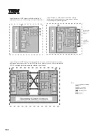
xSeries 440 provides four drive bays on the lower front panel of the system chassis. At the bottom, two adjacent slim-line bays contain the standard CD-ROM and a
1.44MB diskette drive. Two 3.5in, SCA-2-compliant slim-line hot-swap hard disk drive bays are located directly above. The IDE CD-ROM is cabled directly to the IDE
port on the planar, and the hot-swap backplane that supports two hot-swap bays is connected to one channel of the dual channel integrated SCSI controller
through a 16-bit LVDS cable.
An optional ServeRAID controller is supported for internal and external RAID applications. An additional, longer 16-bit LVDS SCSI cable is provided standard with the
system to connect the hot-swap backplane to the ServeRAID controller for internal RAID configurations. The integrated controller includes a second channel that
supports external tape enclosures. A 16-bit LVDS cable connects this channel to an industry-standard, 0.8mm VHDCI connector.
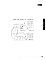
For additional information regarding internal cabling, refer to Appendix F: Internal Cabling Overview.
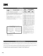
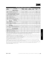
xSeries 440 Memory
Part
Number
Memory Description
1
Total
Memory
1
Quantity of RDIMMs
Added
2, 4
33L3324
512MB PC133 ECC SDRAM RDIMM
2GB
(4 x 512MB)
3
512MB
(33L3324)
1GB
(31P8300)
31P8300
1GB PC133 ECC SDRAM RDIMM
4GB
3
4
-
1. Due to four-way interleaving, installation of memory options in banks of four is required.
Banks may be populated in any order. A minimum of four RDIMMs are required for each
SMP Expansion Module (minimum of eight required to enable memory mirroring).
6GB
8
-
Notes:
8GB
12
-
1. See numbering of RDIMM sockets on memory card for bank configuration.
2. Performance is optimized by balancing the amount of memory between ports (and
between SMP Expansion Modules).
3. In order to enable memory mirroring during BIOS set-up, the same memory
configuration must be installed in each port (memory mirroring reduces the amount of
memory available to the operating system by half).
4. Memory mirroring is specific to each SMP Expansion Module, i.e., it is not required in
both the standard and optional CPU/memory boards.
10GB
8
4
12GB
4
8
14GB
-
12
16GB
4
28
-
18GB
4
24
4
20GB
4
20
8
22GB
4
16
12
24GB
4
12
16
26GB
4
8
20
28GB
4
4
24
30GB
4
-
28
32GB
5
-
32
This table does not represent all possible memory
configurations. RDIMMs must be added in sets of four to
support interleaving technology.
1. Network operating systems may limit the maximum amount
of addressable memory. See operating system specifications
for further information.
2. To obtain the quantity of memory identified in the “Total
Memory” column, select the appropriate row and order the
quantity of RDIMMs identified in all columns for that row, which
will be added to the standard memory noted at the top of the
left column.
3. Model 4RY ships with 4GB of memory standard (4 x 512MB
RDIMMs installed in each SMP Expansion Module).
4. Optional xSeries SMP Expansion Module (P/N 01R1338) is
required if total RDIMMs exceed 16.
5. Requires removal of standard memory. Installation of greater
than 16 RDIMMs requires optional xSeries SMP Expansion
Module (P/N 01R1338).
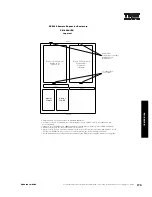
xSeries 440 Internal SCSI Cabling
1 2
9
3
4
5
6
7 8
10 11 12 13 14 15 16
port 1: RDIMM 1-8
port 2: RDIMM 9-16
front of planar
back of planar
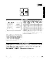
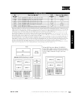
Numbering of RDIMM sockets on memory card
Bank 1: sockets 1, 3, 5, 7
Bank 2: sockets 9, 11, 13, 15
Bank 3: sockets 2, 4, 6, 8
Bank 4: sockets 10, 12, 14, 16
Содержание 6219 - IntelliStation M - Pro
Страница 179: ...Updated 02 Dec 02 141B...
Страница 243: ...BladeCenter HS20 this page intentionally blank this page intentionally blank Updated 02 Dec 02 191B...
Страница 273: ...IBM Rack Cabinets and Options this page intentionally blank this page intentionally blank Updated 02 Dec 02 217B...
Страница 282: ...226 Refer to the cable labeling key in the Cable Options table appearing later in this section...
Страница 283: ...227...

