25
5
F
o
r th
e
la
te
st
pr
o
du
c
t &
t
e
c
h
n
ic
a
l i
n
fo
rma
tio
n
,
re
fe
r to
t
h
e
In
fo
rm
a
tio
n
So
u
rc
e
s
o
n
p
a
g
e
s
2
a
n
d
3
.
U
pd
a
ted
12
/03/
02
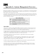
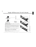
System Management
Overview
To system planar
1
2
3
4
1
2
3
4
6
5
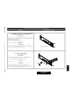
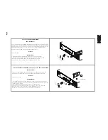
5. Server with ISMP plus optional RSA
Key Features:
Adding an RSA to a server containing an ISMP merges their functionality. The RSA manages
the ISMP and handles communications.
Only applicable to ISMP with firmware v1.02 or later
Servers
xSeries 232, 235, 255, 335 (see note below),342, 345
Instructions:
1. Insert RSA into PCI connector on System Planar (see system I/O section for slot restrictions).
2. Connect 20-pin ribbon cable between system planar and RSA.
3. Insert pigtail cable into RS-485 port on adapter panel.
4. Attach customer-supplied Cat5 cables (for connection to one or two other ASM
interconnect nodes) to the RS-485 ports of the pigtail adapter. Unused
RS-485 ports must be terminated with the supplied RS-485 terminator.
Note: Refer to x335 I/O Options for more information on C2T Interconnect cable chaining
technology connections supporting system management.
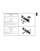
6. Server with standard ASMP and two integrated RS-485 ASM
interconnect ports on the rear of the server chassis, into which
an ASMA is installed
Key Features:
Adding an ASMA to a server containing an ASMP enables the ASMP to access the additional
communication methods available on ASMA hardware. The ASMP retains full control of the
system management role, with the ASMA acting as a gateway between system management
and Ethernet. Requires purchase of optional ASM PCI Adapter (P/N 01K7209).
Servers:
xSeries 230, 330 (8654 models), 350
Instructions:
1. Install ASMA into PCI slot on system planar (see system I/O section for slot restrictions).
2. Plug the pigtail adapter into the RS-485 interconnect port of the ASMA.
3. Attach one end of the 1ft Cat5 cable (included with the ASMA option) to one of the RS-485
ports of the pigtail cable.
4. Attach the other end of the included 1ft Cat5 cable to one of the RS-485 ports built into the
chassis.
5. Attach the customer-supplied Cat5 cable into the other RS-485 port of the pigtail cable.
6. If interconnection to a second ASM interconnect node is required, plug a second
interconnect cable into the available integrated RS-485 port at the rear of the chassis.
Otherwise, the second RS-485 port should be terminated using the supplied
RS-485 terminator.
7. Connect the external AC power supply provided with the option.
Содержание 6219 - IntelliStation M - Pro
Страница 179: ...Updated 02 Dec 02 141B...
Страница 243: ...BladeCenter HS20 this page intentionally blank this page intentionally blank Updated 02 Dec 02 191B...
Страница 273: ...IBM Rack Cabinets and Options this page intentionally blank this page intentionally blank Updated 02 Dec 02 217B...
Страница 282: ...226 Refer to the cable labeling key in the Cable Options table appearing later in this section...
Страница 283: ...227...


