188
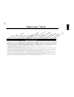
BladeCenter™
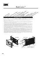
BladeCenter™ At-A-Glance
8677-1XX
Rack
(7U)
1
2/4
2
P, B
3
, B
S-Blowers
S-Power
1/1
4
10/100/
1000
5
4/4
24x-10x
USB
1.44MB
USB
14/14
0/0
6
49P2654
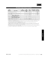
Notes:
A fully configured eServer BladeCenter™ chassis doubles the density of 14 equally configured 1U xSeries 335 servers by accommodating up to 14
BladeCenter HS20 units installed in a 7U rack space.
BladeCenter™ increases usability and reduces complexity because it provides common sourcing for up to 14 BladeCenter HS20 units for cabling and cabling
connections, I/O options, power modules, system management requirements (optional adapters and external cabling), external Fibre Channel storage
switching and connectivity, and network management and expansion.
1. Housed in a 7U, 19in rack-mountable chassis (28in deep). See Rack Cabinets and Options section for supported IBM racks.
2. N+N power supply redundancy is provided standard for HS20 bays one through six and all module bays. Two 220v BladeCenter 1200w Power Modules ship
installed in BladeCenter power module bays one and two. Redundant power for bays seven through 14 requires two additional power modules installed in
power module bays three and four, which are both provided in optional BladeCenter 1200w Power Supply Modules (P/N 48P7052). Nonredundant power can be
supplied to all 14 bays by moving power module two from the second bay to the third, which is not recommended.
3. The blade bays in the front of the chassis support hot-swapping of blade servers. A spring-action cover closes the bay opening when the blade server is
removed, allowing the blade to be removed for up to two hours before thermal restrictions require replacement..
4. Comprehensive system management functionality is provided through the standard management module installed in management module bay one, which
communicates with the integrated service processor on each HS20 planar. The management module also acts as a multiplexor for installed HS20 units for
console connectivity (keyboard, video and mouse).
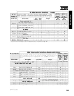
5. One of the dual integrated gigabit Ethernet controllers on each HS20 planar connects to an optional BladeCenter 4-port Gigabit Ethernet Switch Module (P/N
48P7054) installed in switch module bay one. An additional Ethernet switch module may be installed in switch module bay two, to which the second Ethernet
controller integrated into each HS20 planar is connected. Ethernet capability is not provided standard in BladeCenter.
6. BladeCenter contains no PCI expansion slots or HDD bays. Internal HDD expansion is provided in the individual HS20 units. Standard I/O support includes
system management, KVM (console) and Ethernet connectivity. Expanded I/O functionality is provided through optional Fibre Channel switch modules that
install into the BladeCenter chassis. System management functionality is controlled by a system management module, which also installs into the rear system
chassis. Expansion switch modules may not be mixed in a BladeCenter configuration because all HS20 units installed in a single BladeCenter must contain
either the same kind of expansion card or no expansion card. (If an expansion card is installed, only one IDE HDD is allowed.)
7. IBM offers configure-to-order (CTO) capability for selected products through Easy Access. Although similar to machine type models (MTM), CTO systems
utilize different part numbers called Sales Building Blocks (SBB). The contents of an option may not entirely correspond to an SBB because only a certain
component within an option package may be required to configure a specific system. Additional or different configuration rules or limitations may apply to the
SBB. When a difference occurs, the rules will be documented in the tables, diagrams or footnotes.
Op
tio
n
Pa
rt
N
um
be
r
Fo
rm
Fa
ct
or
Po
w
er
M
od
ul
e
Qu
an
tit
y
(S
td
/M
ax
)
Ho
t-s
wa
p
(P
ow
er
, B
ay
s,
B
lo
w
er
s)
Re
du
nd
an
cy
(O
pt
io
na
l,
St
an
da
rd
)
Sy
st
em
M
an
ag
em
en
t M
od
ul
e
(S
td
/M
ax
)
In
te
gr
at
ed
E
th
er
ne
t
Sw
itc
h
M
od
ul
e
Ba
ys
(T
ot
al
/A
va
il)
CD
-R
OM
Fl
op
py
D
is
k
Dr
iv
e
Bl
ad
e
Ba
ys
(T
ot
al
/A
va
il)
PC
I S
lo
ts
/
HD
D
Ba
ys
(T
ot
al
/A
va
il)
SB
B
Nu
m
be
r (
Ea
sy
A
cc
es
s
on
ly
)
7
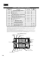
Acoustic Attenuation Module
REAR VIEW
Blades (HS20)
Filler blades
FRONT VIEW
SCSI Storage Expansion Unit
(attached to blade in bay 5)
Blade control
panel
Media tray
(removable)
CD-ROM
FDD
Содержание 6219 - IntelliStation M - Pro
Страница 179: ...Updated 02 Dec 02 141B...
Страница 243: ...BladeCenter HS20 this page intentionally blank this page intentionally blank Updated 02 Dec 02 191B...
Страница 273: ...IBM Rack Cabinets and Options this page intentionally blank this page intentionally blank Updated 02 Dec 02 217B...
Страница 282: ...226 Refer to the cable labeling key in the Cable Options table appearing later in this section...
Страница 283: ...227...

