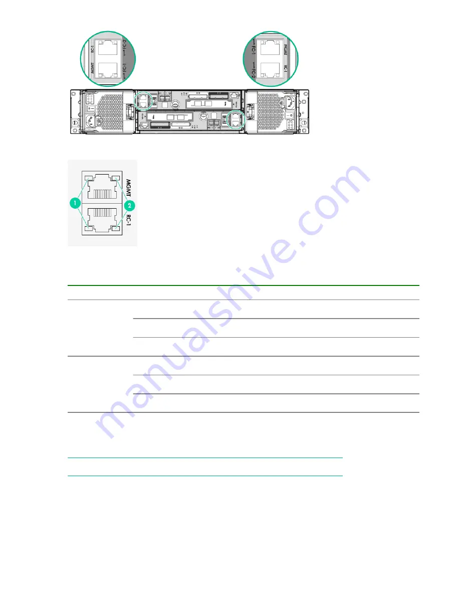
Figure 93: Ethernet onboard ports, controller node enclosure rear view
Figure 94: Ethernet onboard ports LEDs, controller node enclosure rear view
Table 25: Ethernet onboard ports LEDs, controller node enclosure rear view
LED function
Status
State
1
Link up
speed
Green solid
1 Gb Link
Amber solid
100 Mb Link
Off
No link established or 10 Mb Link
2
Activity
Green solid
No link activity
Green flashing
Link activity
Off
No link established
FC onboard ports LEDs, controller node enclosure rear view
The controller node has two Fibre Channel (FC) onboard ports and each port includes two LEDs. The
arrow head-shaped LEDs point to the port they are associated with.
NOTE:
Incorrectly configured cables result in illuminated amber LEDs on the ports.
More information
115


