Hitachi RCI-1.0FSR Скачать руководство пользователя страница 20

1 General information

Product classification and line-up

SMGB0137 rev.0 - 05/2021

10

1.4.6 

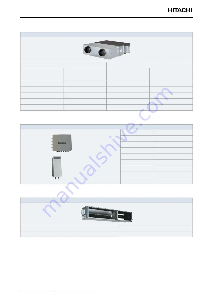
Product line-up: KPI energy recovery unit

KPI

Energy recovery

Active (Energy R R410A DX section)

Unit

Code

Unit

Code

KPI-252E4E

70603000

KPI-502E4E

70603001

KPI-502X4E

70603201

KPI-802E4E

70603002

KPI-802X4E

70603202

KPI-1002E4E

70603003

KPI-1002X4E

70603203

KPI-1502E4E

70603004

KPI-2002E4E

70603005

1.4.7 

Product line-up: DX-Interface

DX-Interface (R410A)

 Control box

 Expansion valve box

Unit

Code

EXV-2.0E2

7E611000

EXV-2.5E2

7E611001

EXV-3.0E2

7E611002

EXV-4.0E2

7E611003

EXV-5.0E2

7E611004

EXV-6.0E2

7E611005

EXV-8.0E2

7E611006

EXV-10.0E2

7E611007

1.4.8 

Product line-up: Econofresh

Econofresh (R410A)

Unit

Code

EF-456N1E

7E560001

?

N O T E

The EF-456N1E unit can only be installed in combination with the following units:
•  RPI-4.0FSN6E-EF (7E426027)
•  RPI-5.0FSN6E-EF (7E426028)
•  RPI-6.0FSN6E-EF (7E426029)

Содержание RCI-1.0FSR

Страница 1: ...OOR UNITS SYSTEM FREE SERIES COMPLEMENTARY SYSTEMS SMGB0137rev 0 05 2021 MODELS SYSTEM FREE RCI FSR RCIM FSRE KPI E X 4E DX Interface EXV E2 Econofresh EF456FSN6E COMPLEMENTARY SYSTEMS RCD FSR RPC FSR RPK FSR H M RPF FSN2E RPFI FSN2E RPI L H FSRE ...

Страница 2: ......

Страница 3: ...B0137 rev 0 05 2021 I 1 2 3 4 5 6 7 8 9 Contents General information Optional accessories Electrical and control settings Control system Optional functions Commissioning Servicing Troubleshooting Maintenance notes ...

Страница 4: ......

Страница 5: ...d remote controls 15 1 4 14 Building air conditioning controls 15 1 4 15 Gateways for building management systems BMS 16 1 4 16 Control support devices 17 1 4 17 Control accessories 17 2 Optional accessories 19 2 1 Duct adapter Outdoor air inlet 20 2 1 1 For RCI FSR indoor units OACI 160K2 and PD 75A 20 2 1 2 For RCIM FSRE indoor units PD 75C 23 2 1 3 For RCD FSR indoor units PD 150D 24 2 2 T duct...

Страница 6: ...ical wiring 56 3 2 Setting of DIP switches and RSW switches 59 3 3 Wiring diagrams 62 3 3 1 RCI 1 0 6 0 FSR 62 3 3 2 RCIM 0 4 2 5 FSRE 63 3 3 3 RCD 0 8 6 0 FSR 64 3 3 3 1 RCD 0 8 3 0 FSR 64 3 3 3 2 RCD 4 0 6 0 FSR 65 3 3 4 RPC 1 5 6 0 FSR 66 3 3 5 RPI L H 0 4 6 0 FSRE 67 3 3 6 RPI 4 0 6 0 FSN6E EF 68 3 3 7 RPI 8 0 10 0 FSN3E f 69 3 3 8 RPI 16 0 20 0 FSN3PE f 70 3 3 9 RPK 0 4 1 5 FSRM 71 3 3 10 RPK...

Страница 7: ... optional input signals 98 5 1 5 Description of optional output signals 104 5 2 Optional functions through Remote control 107 5 2 1 List of optional remote control functions PC ARFP1E 107 5 2 2 Description of the optional remote control functions PC ARFP1E 126 5 2 3 Optional functions for PC ARH1E remote controls 142 5 2 4 Description of the optional remote control functions PC ARH1E 156 5 2 5 Ala...

Страница 8: ...c louver motor 200 7 3 RCD 0 8 6 0 FSR 2 way cassette 201 7 3 1 Removal of the air filter and the air inlet grille 201 7 3 2 Removal of the electrical box 203 7 3 3 Removal of the optional air panel 204 7 3 4 Removal of the fan duct and the fan 204 7 3 5 Removal of the printed circuit board PCB 206 7 3 6 Removal of the float switch 207 7 3 7 Removal of the drain mechanism 207 7 3 8 Removal of the ...

Страница 9: ...ver 248 7 7 4 Remove the switch cover 249 7 7 5 Replacing DIP Switch PCB PCB2 249 7 7 6 Replacing PCB1 for control 250 7 7 7 Removing AS motor 251 7 7 8 Removing drain pan 252 7 7 9 Removing heat exchanger 253 7 7 10 Removing thermistors for freeze protection gas pipe outlet air and inlet air 257 7 7 11 Removing fan and fan motor 261 7 7 12 Removing electronic expansion valve coil 264 7 7 13 Remov...

Страница 10: ...ance notes 287 9 1 Regular equipment maintenance 288 9 1 1 Necessary tools equipment and consumable for regular maintenance 288 9 2 Indoor cleaning 289 9 2 1 Cleaning the built in 4 way indoor unit RCI M 289 9 2 2 Cleaning the built in 2 way indoor unit RCD 292 9 2 3 Cleaning of the wall type indoor unit RPK 294 9 2 4 Cleaning the floor console and floor concealed console indoor unit RPF I 295 9 2...

Страница 11: ...fication of Econofresh models 4 1 4 5 Product line up indoor units 5 1 4 6 Product line up KPI energy recovery unit 10 1 4 7 Product line up DX Interface 10 1 4 8 Product line up Econofresh 10 1 4 9 Accessory code list 11 1 4 10 Multi Kits 13 1 4 11 Individual remote controls 13 1 4 12 Receiver kit for combination with wireless remote control switch 14 1 4 13 Centralised remote controls 15 1 4 14 ...

Страница 12: ... to offer correct up to date documentation Despite this printing errors cannot be controlled by Hitachi and are not its responsibility As a result some of the images or data used to illustrate this document may not refer to specific models No claims will be accepted based on the data illustrations and descriptions included in this manual No type of modification must be made to the equipment withou...

Страница 13: ...tems may also be included 1 3 Norms and Regulations Following Regulation EU Nº 517 2014 on Certain Fluorinated Greenhouse gases it is mandatory to fill in the label attached to the unit with the total amount of refrigerant charged on the installation Do not vent R32 into the atmosphere R32 is fluorinated greenhouse gas covered by the Kyoto protocol global warming potential GWP R32 675 Do not vent ...

Страница 14: ...PI 8 0 20 0 FSN3 P E f only EF Ducted indoor unit for econofresh assembly RPI 4 0 6 0 FSN6E EF only XXX X X X FS X H X P X X 1 4 2 Classification of KPI models KPI Ventilation system Position separating hyphen fixed Capacity m3 h 250 500 800 1000 1500 2000 2 1 230V 50Hz E Energy recovery X Active Energy recovery R410A DX section 4 series E Made in Europe KPI Y YY 2 Y 4 E 1 4 3 Classification of DX...

Страница 15: ...5FSR 70405304 RCIM 2 5FSRE 7E414104 RCI 3 0FSR 70405305 RCI 4 0FSR 70405307 RCI 5 0FSR 70405308 RCI 6 0FSR 70405309 Panel Panel P N23NA2 without Motion Sensor 70532000 P AP56NAM without Motion Sensor 70533000 P AP160KA3 Standard panel without Motion Sensor black 60279337 P AP56NAMS Motion Sensor embedded 70533100 P GP160NAP Iconic panel white 60297331 P AP56NAMR Receiver kit embedded 70533500 P GP...

Страница 16: ... 2 0FSR 60279171 RPC 2 0FSR 60279268 RCD 2 5FSR 60279172 RPC 2 5FSR 60279269 RCD 3 0FSR 60279173 RPC 3 0FSR 60279270 RCD 4 0FSR 60279174 RPC 4 0FSR 60279271 RCD 5 0FSR 60279175 RPC 5 0FSR 60279272 RCD 6 0FSR 60279176 RPC 6 0FSR 60279273 Panel Panel P AP90DNA 60297319 P AP160DNA 60297320 N O T E The RCD models must be used in combination with the indicated panels 1 indoor unit combinations with UTO...

Страница 17: ... 0FSN3E 3 RPI 8 0FSN3E f 3 7E424010 7E424410 RPI 10 0FSN3E 3 RPI 10 0FSN3E f 3 7E424011 7E424411 RPI 16 0FSN3PE 4 RPI 16 0FSN3PE f 4 7E425038 7E425438 RPI 20 0FSN3PE 4 RPI 20 0FSN3PE f 4 7E425039 7E425439 N O T E 1 Follow the detailed information about the combinability and restrictions for 0 4 HP Indoor Units which can only be used in combination with current SET FREE RAS FSXNSE RAS FSXNPE and SI...

Страница 18: ...al information Product classification and line up SMGB0137 rev 0 05 2021 8 DUCTED INDOOR UNIT for ECONOFRESH ASSEMBLY R410A Unit Code RPI 4 0FSN6E EF 7E426027 RPI 5 0FSN6E EF 7E426028 RPI 6 0FSN6E EF 7E426029 ...

Страница 19: ...M 60279209 RPF 2 0FSN2E 3 7E450003 RPFI 2 0FSN2E 3 7E460003 RPK 2 5FSRM 60279210 RPF 2 5FSN2E 3 7E450004 RPFI 2 5FSN2E 3 7E460004 RPK 3 0FSRM 60279211 RPK 4 0FSRM 60279212 Expansion valve kit 4 EV 1 5N1 4 60921792 N O T E 1 Follow the detailed information about the combinability and restrictions for 0 4 HP Indoor Units which can only be used in combination with current SET FREE Mini RAS 4 6 FS V N...

Страница 20: ... 70603203 KPI 1502E4E 70603004 KPI 2002E4E 70603005 1 4 7 Product line up DX Interface DX Interface R410A Control box Expansion valve box Unit Code EXV 2 0E2 7E611000 EXV 2 5E2 7E611001 EXV 3 0E2 7E611002 EXV 4 0E2 7E611003 EXV 5 0E2 7E611004 EXV 6 0E2 7E611005 EXV 8 0E2 7E611006 EXV 10 0E2 7E611007 1 4 8 Product line up Econofresh Econofresh R410A Unit Code EF 456N1E 7E560001 N O T E The EF 456N1...

Страница 21: ...oor air outlet 60299436 PDF 160C1 RCI 3 0 6 0 FSR 60299437 PI 160LS1 RCI FSR 3 way outlet parts set 60291756 B 160H2 RCI FSR Filter Box Adapter for deodorising filter 60291759 F 71L D1 RCI 1 0 2 5 FSR Deodorant air filter installation on the Filter Box B 160H2 60291757 F 160L D1 RCI 3 0 6 0 FSR 60291758 B 90HD RCD 0 8 3 0 FSR Filter Box Adapter for antibacterial long life air filter 60292061 B 160...

Страница 22: ...E 4E Noise damper 70550200 SLT 30 250 L600 KPI 802 X E 4E 70550201 SLT 30 300 L600 KPI 1002 X E 4E 70550202 SLT 30 355 L600 KPI 1502 2002 E4E 70550203 HEF 252 KPI High efficiency filter 70552201 HEF 502 70552202 HEF 802 70552203 HEF 1002 70552204 HEF 1502 70552205 HEF 2002 70552206 D ICA15R RPIL 0 4 1 5 FSRE Inlet change accessory 7E590912 D ICA20R RPI 1 5 2 0 FSRE 7E590913 D ICA30R RPI 2 5 3 0 FS...

Страница 23: ...02SN3 70524105 MW NP2682A3 60292295 E 52XN3 70525100 E 102XN3 70525101 E 162XN3 70525102 E 202XN3 70525103 E 242XN3 70525104 E 322XN3 70525106 MH 84AN1 Header Branch 70522009 MH 108AN 70522008 MH 108XN 70523108 1 4 11 Individual remote controls Name Description Code Figure PC ARFP1E Remote control with timer 70510003 PC ARH1E Simplified remote control 70510004 PC AWR Wireless remote control 602919...

Страница 24: ...eiver kit name Indoor unit application Compatible wireless remote control Code Figure on the panel PC ALH3 RCI FSR PC AWR 60291767 PC ALHC1 RCIM FSRE PC AWR 70590906 PC ALHD1 RCD FSR PC AWR 60292053 PC ALHP1 RPC FSR PC AWR 60291823 on the wall PC ALHZ1 RPI L H FSRE EF RPI FSN 3 6 P E f RPF I FSN2E RCI FSR RCIM FSRE RCD FSR RPK FSR H M RPC FSR PC AWR 60292245 ...

Страница 25: ...ed control with a touch interface of 10 inches which runs CSNET Manager 2 software to control the indoor units 7E512203 CSNET Manager 2 T15 Centralised control with a touch interface of 15 inches which runs CSNET Manager 2 software to control the indoor units 7E512206 CSNET Manager 2 SL Centralised control interface screen less which runs CSNET Manager 2 software to control the indoor units 7E5122...

Страница 26: ...NX 16 Integration with installations with intelligent control BMS through CSNET Manager 2 and CSNET Lite Gateway Interface to KNX systems 70513303 HI AC KNX 64 Integration with installations with intelligent control BMS through CSNET Manager 2 and CSNET Lite Gateway Interface to KNX systems 70513304 HARC BX E A Integration with installation with intelligent control Building Management System Gatew...

Страница 27: ... Control accessories Name Description Code Figure Wall support 2 Wall mounted support for both CSNET Manager 2 T10 T15 7E512302 Stand support Stand mounted support for both CSNET Manager 2 T10 T15 7E512301 Din rail Standard din rail for CSNET Lite 7E512303 PCC 1A Optional function connector 70590901 PRC 10E1 2P Extension cord 10 metres 7E790211 PRC 15E1 2P Extension cord 15 metres 7E790212 PRC 20E...

Страница 28: ......

Страница 29: ...26 2 4 Outlet air flow interlock 27 2 4 1 For RCI FSR indoor units PI 160SL1 27 2 5 Filter box 29 2 5 1 For RCI FSR indoor units B 160H2 29 2 5 2 For RCD FSR indoor units BD 90H and BD 160HD 30 2 6 Anti bacteria filter 31 2 6 1 For RCI FSR F 160L K 31 2 6 2 For RCD FSR indoor units F 90MD K1 and F 160MD K1 Antibacterial long life air filter 32 2 7 Deodorising filter 32 2 7 1 For RCI FSR indoor uni...

Страница 30: ...xiliary Relay Total heat exchanger or magnetic switch Indoor unit printed circuit board Auxiliary relay Remarks for OACI 160K2 The standard maximum air volume of fresh air intake when using the outdoor air inlet duct reference OACI 160K2 combined with a total heat exchanger or the duct fan is within 20 of the rated air volume of the indoor unit at HIGH mode If the amount of incoming outdoor air ex...

Страница 31: ...air intake m3 min 1 0 2 5 HP 1 0 3 0 6 0 HP 2 0 The outdoor air inlet duct reference PD 75A resistance data is indicated in the following figure Use as a guide for fan selection 40 20 0 0 1 2 60 Air flow volume Pass resistance Example of the duct fan installation Nº Part 1 Duct made of non combustible materials only 2 Thermal insulation non combustible materials 3 Outdoor air inlet hood with galle...

Страница 32: ...on Air panel side Indoor unit side Fresh air total heat exchanger Fresh air total heat exchanger N O T E The total height of the unit is increased by around 55 mm when the outdoor air inlet duct OACI 160K2 is installed Take this measurement into account when installing the unit Dimensions a b 12 55 Min 10 50 5 840 155 φ75 P φ75 φ75 760 840 760 705 840 40 85 Installation height Fresh air intake kit...

Страница 33: ...4 137 840 Electrical box Duct adaptor Fresh air intake Screw 4 portions accessory Packing accessory Indoor unit HP a 1 0 2 5 248 3 0 6 0 298 2 1 2 For RCIM FSRE indoor units PD 75C The inlet of outdoor air is possible through the PD 75C duct adapter for RCIM FSRE indoor units PD 75C RCIM FSRE Ø75 Outer diameter 137 6 121 67 6 8 Insulation 112 9 Only 1 duct adapter can be installed HP a 0 4 2 5 248...

Страница 34: ...r intake duct 630 315 144 Duct adapter Duct adapter Indoor unit Fresh air Duct Ø150 Duct band Screw x4 Fresh air intake Total heat exchanger Indoor unit Duct adapter Wrap by insulation to prevent air leakage Inside Outside Install a net at the inlet to prevent small animals to enter into the duct Install a hood to prevent water contamination Field supplied Down slop 1 50 to 1 100 Ø 150 Field suppl...

Страница 35: ... 179 3 0 6 0 353 229 840 664 P 210 118 φ145 124 Min 10 a b 840 Electrical box Air flow Fresh air intake kit View from P Flexible duct 150 field supplied Air flow Fresh air Total heat exchanger Suspension band Field supplied Fresh air Total heat exchanger Indoor unit Indoor unit The outdoor air inlet duct resistance increases as indicated in the following figure when using the T duct connection Use...

Страница 36: ...e Example of branched duct Branch pipe installation The connections for the branch pipe are indicated in the following figure There are six knock out holes Cut the insulation material on the outer surface in a circle and line up the notches at the four corners Use a screwdriver or similar and remove Prepare the square connection duct field supplied or use a flexible duct with a diameter of 150 or ...

Страница 37: ...ble insulating materials 3 Fit enough heat insulation to the duct to avoid condensation 4 Follow the regulations in force regarding this matter in the place of installation or use the dimensions indicated in the figure below if there are no applicable regulations Main body Measurement Wall and pillar material Combustible materials Non combustible materials A 100 mm 50 mm B 100 mm 60 mm 2 4 Outlet ...

Страница 38: ...40 435 470 440 380 340 340 Blocking Part Piping side RCI 1 0 6 0 FSR Refer to the item 1 3 Way Outlet for the size of blocking plate of each model 1 Change the position of the outlet temperature thermistor If not the room temperature adjustment may not be available 2 In the case of Example 3 the air flow volume will decrease compared with other cases Set the high speed setting Example for 3 Way an...

Страница 39: ...panel side Packing EPDM 10 Before compression 5 After compression Installation height Insulation Polyethylene When the filter box is installed the total height of the unit increases by approximately 55 mm Therefore pay attention to the installation space Bear in mind that the size before compression is 10 mm but the size is reduced after compression to 5mm 840 55 12 50 a b 5 155 Min 10 Packing Ind...

Страница 40: ...T E The filters are sold separately Dimensions mm Model a BD 90HD 850 BD 160HD 1410 Service space 417 630 8 300 49 60 68 10 Long life filter Air inlet flat grille Air panel Attached with optional air panel Ceiling Filter box option Air filter Indoor unit Installation height After compression Min Specifications B 90HD B 160HD Item RCD 0 8 3 0 FSR RCD 4 0 6 0 FSR Quantity 1 Installation height mm 68...

Страница 41: ... square holes into the extruded parts of air inlet grille Model a mm RCI 1 0 2 5 FSR 238 RCI 3 0 6 0 FSR 288 Specifications Part RCI 1 0 6 0 FSR Dust collection efficiency 50 gravimetric method Air flow rate m3 min 35 0 Initial pressure loss Pa 28 0 Final pressure loss Pa 62 0 Filter Frame colour White Brown Working life 4 years with maintenance every 1250 hours Cleaning Available Weight kg 0 6 Pe...

Страница 42: ...MD K1 A F 90MD K1 A B Air volume m3 min Pressure Loss Pa Dust collection efficiency 65 Gravimetric method 1 Air flow m3 min 19 5 32 5 Initial pressure Loss Pa mmAq 17 0 20 5 End pressure Loss Pa mmAq 55 9 62 8 Colour Filter frame White Brown Life period 8 years with 2500 hours maintenance Cleaning Not available Accessory Installation manual Weight kg 0 9 0 8 x 2 Performance Avoids the multiplicati...

Страница 43: ...ressure loss Pa 19 0 36 0 Final pressure loss Pa 48 0 78 0 Filter frame colour Pink Silver Working life 3 years with maintenance every 3 6 months Reuse Available dried by sunlight 1 Cleaning Available washed with water 2 Weight kg 0 8 1 2 Performance Absorbs smoke body odour etc Filter material Antibacterial fiber Acrylate Fiber 1 Absorbed fiber for basic gas Acrylate Fiber 2 Absorbed fiber for ac...

Страница 44: ...entire RPI L FSRE range This change of air inlet from the back side to the bottom side can be achieved by adding an optional accessory specifically designed for this purpose Inlet air direction Inlet cover Bottom cover Inlet Change Accessory Kit Inlet Change Accessory Kit N O T E Inlet change accessory codes D ICA15R 7E590912 RPIL 0 4 1 5 FSRE D ICA20R 7E590913 RPI 1 5 2 0 FSRE D ICA30R 7E590914 R...

Страница 45: ... 9 1 For RPIL 0 4 1 5 FSRE units On RPIL models it is optionally possible to change the drainage system by disabling the drainage pump and installing a gravity drainage kit Example of both possible drainage connections with Drain Pump option and Gravity drain kit Gravity drain connection Drain pump connection ...

Страница 46: ......

Страница 47: ...52 3 1 9 Electrical connection of KPI units 54 3 1 10 Econofresh electrical wiring connection 55 3 1 11 DX Interface electrical wiring 56 3 2 Setting of DIP switches and RSW switches 59 3 3 Wiring diagrams 62 3 3 1 RCI 1 0 6 0 FSR 62 3 3 2 RCIM 0 4 2 5 FSRE 63 3 3 3 RCD 0 8 6 0 FSR 64 3 3 3 1 RCD 0 8 3 0 FSR 64 3 3 3 2 RCD 4 0 6 0 FSR 65 3 3 4 RPC 1 5 6 0 FSR 66 3 3 5 RPI L H 0 4 6 0 FSRE 67 3 3 6...

Страница 48: ...d outdoor units are at a standstill before starting work N O T E The electrical power for the unit must involve a specific power line with an exclusive power control switch and residual current breaker installed in line with local or national safety regulations Check that the electrical power line has enough capacity to supply the unit Its length the cable diameter and their protection sleeve or j...

Страница 49: ...crews on terminals L1 and N or L1 and L2 as applicable on the terminal strip TB1 2 Connect the power cables to terminals L1 and N or L1 and L2 as applicable 3 Tighten the screws on terminals L1 and N or L1 and L2 as applicable 4 Check that the cables are correctly secured Follow the steps below to connect the communication cables between the outdoor and indoor unit to the terminal strip TB1 1 Wher...

Страница 50: ...ll during forced stoppage 3 1 3 Electrical connection of RCIM units Before proceeding to any electrical connection 1 Turn off the power supply switches before starting work and fit the appropriate locks and safety warnings 2 Wait 5 minutes after turning off the power supply switches 3 Check that the fans on the indoor and outdoor units are at a standstill before starting work N O T E The electrica...

Страница 51: ...l extension wire 1 Pass the cable through the knock out hole in the cabinet 2 Connect the cable to terminals A and B of the terminal strip TB2 3 Tighten the screw on terminals A and B 4 Check that the cables are correctly secured Follow the steps below to connect the power cables to the terminal strip TB1 C A U T I O N To connect a power supply with neutral connect the cables to terminals L1 and N...

Страница 52: ...cal power for the unit must involve a specific power line with an exclusive power control switch and residual current breaker installed in line with local or national safety regulations Check that the electrical power line has enough capacity to supply the unit Its length the cable diameter and their protection sleeve or jacket must be appropriate for the unit For further information always consid...

Страница 53: ...Fan motor connector 3 Terminal strip TB2 4 Terminal strip TB1 5 Wiring 6 Power wiring Follow the steps below to connect the earth wire to the earth connection in the electrical box 1 Where necessary loosen the screw on the earthing connection in the electrical box 2 Connect the shielded part of the power supply earth wire and the signal wiring earth wire to the earth connection 3 Tighten the screw...

Страница 54: ... electrical components inside the unit to avoid damaging them Loose connection terminals may lead to cable and terminal overheating The unit may operate incorrectly leading to a risk of fire Check that the cables are firmly secured to the connection terminals Electrical connection Check that the power supply for the RPC indoor unit is 230 V If not replace connectors CN on the TF transformers in th...

Страница 55: ...ve when the outdoor unit ducts are not used The compressor remains at a standstill during forced stoppage 3 1 6 Electrical connection of RPI units Work prior to the electrical connection 1 Turn off the power supply switches before starting work and fit the appropriate locks and safety warnings 2 Wait 5 minutes after turning off the power supply switches 3 Check that the fans on the indoor and outd...

Страница 56: ...w to connect the power cables to the terminal strip TB 1 Where necessary loosen the screws on terminals L1 and N on the terminal strip TB 2 Connect the power cables to terminals L1 and N 3 Tighten the screws on terminals L1 and N 4 Check that the cables are correctly secured Remote control PC ARFP1E Power supply wires single phase Transmission wires Earth screw From 0 4 to 6 0 hp Follow the steps ...

Страница 57: ...e hole using a sealant to protect them from condensation and insects Nº Part PCB Printed circuit board TB Terminal strip Wiring connection Electrical box PCB TB RPI 8 0 10 0 FSN3E f Terminal board connections Nº Part PCB1 Printed circuit board PCB2 Printed circuit board TF Transformer TB Terminal strip FUSE Fuse Service panel for electrical box Wiring connection FUSE ...

Страница 58: ...e Static Pressure setting connector CN24 LSP Low Static Pressure or CN25 HSP High Static Pressure the fan speed available in the Remote Control Switch are the ones show as example in the following pictures Example for RPI 8 0 10 0 FSN3E f Static pressure setting HSP Static pressure setting LSP External static pressure Pa Lower ESP limit Low High Med Upper ESP limit External static pressure Pa Lowe...

Страница 59: ...C A U T I O N Make sure that the field selected electrical components main power switches circuit breakers wires conduit connectors and wire terminals have been properly selected according to the electrical data given in Technical Catalogue Make sure that the components comply with National Electrical Code NEC Use the shielded twist pair cable for the control cable between the outdoor unit and the...

Страница 60: ...power supply wiring from the terminal block for controller and communication cables TB2 Do not connect the main power source cables to the control line Terminals A B 1 and 2 of TB2 If connected the printed circuit board PCB will be broken Pay attention to followings when wires are connected to terminal board A Attach an insulation tape or a sleeve to each terminal B Maintain the distance between t...

Страница 61: ...Terminal board for power source Fix the wires by cord clamp DIP switch location PCB2 Switch cover DSW5 RSW1 RSW2 DSW6 DSW9 DSW2 SW2 DSW3 Test runs C A U T I O N Be careful during the test runs as some of the safety functions remain disabled the units operate for two hours without switching off via the thermostat The three minute compressor protection is not enabled during the test Secure the rubbe...

Страница 62: ...stalled C A U T I O N Risk of fire cables must never touch the refrigerant pipes printed circuit boards PCB sharp edges or electrical components inside the unit to avoid damaging them Loose connection terminals may lead to cable and terminal overheating The unit may operate incorrectly leading to a risk of fire Check that the cables are firmly secured to the connection terminals Electrical connect...

Страница 63: ... screw Follow the steps below to connect the communication cables between the outdoor and indoor unit to the terminals in the electrical box 1 Where necessary loosen the screws on the communication terminals in the electrical box 2 Connect the communication cables to communication terminals 1 and 2 in the electrical box 3 Tighten the screws on the communication terminals in the electrical box 4 Ch...

Страница 64: ...the rubber bushing in the wiring connection knock out hole Follow the steps below to connect the remote control cable or the optional extension wire 1 Pass the cable through the knock out hole in the cabinet 2 Connect the cable to the terminals on the printed circuit board PCB located inside the electrical box 3 Tighten the screw on terminals A and B in the electrical box 4 Check that the cables a...

Страница 65: ...as stopped before electrical wiring work or a periodical check is performed Protect the wires electrical parts etc from rats or other small animals If not protected rats may gnaw at unprotected parts and at the worst a fire will occur C A U T I O N Wrap the accessory packing around the wires and plug the wiring connection hole with the seal material to protect the products from any condensate wate...

Страница 66: ... a conduit tube for field wiring is not used fix rubber bushes to the panel with adhesive All the field wiring and equipment must comply with local and international codes When a cable gland is not used it must be sealed properly in order to ensure the correct control box sealing C A U T I O N Pay attention to the connection of the operating line Incorrect connection may cause PCB failure N O T E ...

Страница 67: ... Hz Wire section 3x0 5mm2 1 7 P P PWM output signal 0 100 8 G G GND 9 T EC2 PWM Output control for EC FAN 2 optional T Tach input signal Hz Wire section 3x0 5mm2 1 10 P P PWM output signal 0 100 11 G G GND 12 V DUTY A Duty control by current 4 20mA optional V Output power to device 24Vdc Wire section 3x0 5mm2 N O T E Maximum power by 24Vdc output 3 W 13 D D Current input 4 20mA 14 N N GND 15 1 FS ...

Страница 68: ...remote controller optional N Neutral phase connection common Maximum current allowed 3 5A Wire section 4x0 75mm2 1 14 H H High fan speed signal 15 M M Medium fan speed signal 16 L L Low fan speed signal 17 Not used 18 19 1 M AL Motor alarm signal Alarm input signal can be used for alarm link between the DX Kit interface and the unit connected If the jumper between terminal 1 19 and 2 20 is open un...

Страница 69: ... for the tens digit Address of the indoor unit setting for the tenth digit Address of the indoor unit setting for the tenth digit 1 Turn off the power supply before setting the DIP switches Otherwise the switch settings are invalid 2 To set the position of the RSW rotary switches insert a screwdriver into the groove of the RSW N O T E The DIP and RSW switches of each indoor and outdoor unit must b...

Страница 70: ...t is required to change factory default setting with a value of up to 63 In the same refrigerant cycle set the same refrigerant cycle number for the outdoor unit and the indoor unit DSW6 and RSW 1 2 Unit number setting It is strongly recommended to change factory default setting with any value from 0 up to 63 The address number must be unique for each unit in the same refrigerant cycle All indoor ...

Страница 71: ...RSW switches SMGB0137 rev 0 05 2021 61 3 RPI 16 0 20 0 FSN3PE f only No setting is required DSW6 RSW1 PCB1 Upper E box PCB2 Lower E box 1 2 3 4 5 6 ON N O T E When further connecting indoor units make sure to set a number other than one or two for each indoor unit ...

Страница 72: ...ted circuit board Electrical control box of Indoor unit Service connector for drain discharge mechanism Operation line DC5V Field connection PCB for motion sensor Air Panel Mark Name CA Capacitor CNn Connector on PCB PCNn Power connector on PCB DSW3 9 DIP switch for setting RSW1 2 Rotary switch for setting EFR1 Power supply fuse MIF Motor for Indoor fan MS1 4 Motor for automatic swing louver MV Mi...

Страница 73: ... in EVAP UNIT Wired controller Operation line DC5V Field connection Included in FS Exp Valve Earth Printed circuit board 1 230V 50Hz Mark Name EF2 Fuse MFE Motor for indoor fan MD Motor drain pump MV Electronic expansion valve FS Float switch DSW3 Indoor unit capacity setting DSW4 Model setting DSW5 Refrigerant cycle no DSW6 Indoor unit no DSW7 Transmission recovery RSW1 Refrigerant cycle no RSW2 ...

Страница 74: ...r supply fuse MIF Motor for Indoor fan MS1 2 Motor for automatic swing louver MV Micro computer control expansion valve MD Motor for drain discharge mechanism FS Float switch PCB1 Printed circuit board TB1 2 Terminal board THM1 5 Thermistor Field connection Remote control switch Operating line DC5V Field connection Air panel Electrical control box of Indoor unit Optional Service connectos for Drai...

Страница 75: ...trical control box of Indoor unit Air inlet Air outlet Freeze protection Remote Gas piping Mark Name CNn Connector on PCB PCNn Power connector on PCB DSW3 9 DIP switch for setting RSW1 2 Rotary switch for setting EFR1 Power supply fuse MIF1 2 Motor for Indoor fan MS1 2 Motor for automatic swing louver MV Micro computer control expansion valve MD Motor for drain discharge mechanism FS Float switch ...

Страница 76: ...Printed circuit board Air inlet Air outlet Freeze protection Gas piping Mark Name CA Capacitor CNn Connector on PCB PCNn Power connector on PCB DSW3 9 DIP switch for setting RSW1 2 Rotary switch for setting EFR1 Power supply fuse MIF Motor for Indoor fan MS Motor for automatic swing louver MV Micro computer control expansion valve PCB1 Printed circuit board TB1 2 Terminal board THM1 5 Thermistor 1...

Страница 77: ... evap stay 3 unit Arranged in evap unit Included in TB1 Earth 1N 230V 50Hz Mark Name CNn Connector on PCB PCNn Power connector on PCB RSW1 Refrigerant cycle no RSW2 Indoor unit no EFR1 Power supply fuse EF2 PCB fuse MFE Motor for Indoor fan NF Noise filter MV Micro computer control expansion valve MD Motor drain pump FS Float switch PCB1 Printed circuit board TB1 2 Terminal board MFE Motor for the...

Страница 78: ...f indoor unit PCB1 Sockets location PCB2 Sockets location Service connector for drain discharge mechanism FS Air inlet Air outlet Liquid pipe Gas pipe Arranged in evap stay 3 unit Arranged in evap unit Included in TB1 1 230V 50Hz Mark Name CA Capacitor CNn Connector on PCB PCNn Power connector on PCB DSW3 9 DIP switch for setting RSW1 2 Rotary switch for setting EFR1 Power supply fuse EF2 PCB fuse...

Страница 79: ...switch for setting RSW1 2 Rotary switch for setting EFR1 Power supply fuse EF1 Fuse for PCN5 connector EF2 Fuse for fans located in the terminal box EF4 PCB fuse MIF Motor for Indoor fan MV Micro computer control expansion valve MD Motor for drain discharge mechanism FS Float switch PCB1 2 Printed circuit board TB Terminal board THM1 5 Thermistor Mark Name TF Transformer ITI Internal thermostat fo...

Страница 80: ...e THM1 5 Thermistor TF TF2 Transformer ITI Internal thermostat for indoor fan motor CN20 31 Aerial connector indoor unit 1 CN202 312 Aerial connector indoor unit 2 RCS Remote control switch TB TB2 Terminal board TF TF2 Transformer X2 High speed terminal X3 Medium speed terminal X4 Low speed terminal X5 S Low speed terminal PCB1 12 Printed circuit board indoor unit 1 PCB2 22 Printed circuit board i...

Страница 81: ...or emergency operation EFR1 Power supply fuse Mark Name EFS1 Power supply fuse MIF Motor for Indoor fan MS Motor for automatic swing louver MV Micro computer control expansion valve PCB1 2 3 Printed circuit board TB1 2 Terminal board THM1 5 Thermistor PCB1 PCB2 PCB3 Air inlet Air outlet Freeze protection Gas piping Wired remote control switch Wireless remote control switch Operation line DC 5V Wir...

Страница 82: ...ctor on PCB PCNn Power connector on PCB DSW2 9 DIP switch for setting RSW1 2 Rotary switch for setting SW2 Switch for changing wired wirelles controller PSW802 Switch for emergency operation EFR1 Power supply fuse Mark Name EFS1 Power supply fuse MIF Motor for Indoor fan MS Motor for automatic swing louver MV Micro computer control expansion valve PCB1 2 3 Printed circuit board TB1 2 Terminal boar...

Страница 83: ...e CNn Connector on PCB PCNn Power connector on PCB DSW2 9 DIP switch for setting RSW1 2 Rotary switch for setting SW2 Switch for changing wired wireless controller PSW1 Switch for emergency operation EFR1 Power supply fuse Mark Name EFS1 Power supply fuse MIF Motor for Indoor fan MS1 2 Motor for automatic swing louver MV Micro computer control expansion valve PCB1 2 3 Printed circuit board TB1 2 T...

Страница 84: ...nnector on PCB DSW3 7 DIP switch for setting RSW1 2 Rotary switch for setting EFR1 Power supply fuse EF2 PCB fuse EF3 Fuse for PCN5 connector MIF Motor for Indoor fan MV Micro computer control expansion valve PCB Printed circuit board Mark Name TB1 2 Terminal board THM1 5 Thermistor TF Transformer ITI Internal thermostat for indoor fan motor CN22 27 Aerial connector YH1 Relay for HI fan motor tap ...

Страница 85: ... MS1 2 Motor for automatic swing louver MV Micro computer control expansion valve FS Float switch PCB1 2 Printed circuit board TB1 2 Terminal board THM1 5 Thermistor NF1 Noise filter TF Transformer CN23 30 Aerial connector RCS Remote control switch DMP Damper SEGn 7 segments display PSW1 3 Push button OA Outdoor air RA Return air 1 230V 50 Hz Main switch CB fuse ELB Main PCB Air Outlet Air inlet L...

Страница 86: ... on PCB DSW3 7 DIP switch for setting RSW1 2 Rotary switch for setting EFR1 Power supply fuse EF2 PCB fuse EF3 Fuse for PCN5 connector MIF1 2 Motor for Indoor fan MV Micro computer control expansion valve MD Motor for drain discharge mechanism FS Float switch PCB1 2 Printed circuit board TB1 2 Terminal board THM1 5 Thermistor TF Transformer ITI Internal thermostat for indoor fan motor RCS Remote c...

Страница 87: ... for RPI 4 0 6 0 FSN6E EF PI114 PI117 83 4 7 Printed circuit board for RPI 8 0 20 0 FSN3 P E f units PI065 PI005 84 4 8 Printed circuit board for RPK FSR H M units 85 4 8 1 For RPK 0 4 1 5 FSR H M PI151 PI154 85 4 8 2 For RPK 2 0 4 0 FSRM PI151 PI154 86 4 9 Printed circuit board for RPF I FSN2E units PI073 87 4 10 Printed circuit board for complementary systems 88 4 10 1 Printed circuit board for ...

Страница 88: ...ellow This LED indicates the transmission status between the indoor unit and the outdoor unit LED4 Red PCB power supply LED5 Red PCB power supply high voltaje LED6 Green Not used Connector indication TB1 Terminal board Power TB2 Terminal board Control EFR1 Fuse 5A EF2 Fuse 0 5A PCB1 Printed circuit board NF1 Noise filter THM1 Air inlet thermistor THM2 Air outlet thermistor THM3 Liquid pipe thermis...

Страница 89: ...D6 Green Not used Connector indication TB1 Terminal board Power TB2 Terminal board Control EFR1 Fuse 5A EF2 Fuse 0 5A PCB1 Printed circuit board NF1 Noise filter THM1 Air inlet thermistor THM2 Air outlet thermistor THM3 Liquid pipe thermistor THM4 Optional connector for remote temperature sensor THM5 Gas pipe thermistor CN1 Printed circuit board 2 CN2 Terminal board CN3 Optional input functions CN...

Страница 90: ...d Connector indication TB1 Terminal board Power TB2 Terminal board Control EFR1 Fuse 5A EF2 Fuse 0 5A PCB1 Printed circuit board NF1 Noise filter THM1 Air inlet thermistor THM2 Air outlet thermistor THM3 Liquid pipe thermistor THM4 Optional connector for remote temperature sensor THM5 Gas pipe thermistor CN1 Printed circuit board 2 CN2 Terminal board CN3 Optional input functions CN7 Aerial connect...

Страница 91: ...d Connector indication TB1 Terminal board Power TB2 Terminal board Control EFR1 Fuse 5A EF2 Fuse 0 5A PCB1 Printed circuit board NF1 Noise filter THM1 Air inlet thermistor THM2 Air outlet thermistor THM3 Liquid pipe thermistor THM4 Optional connector for remote temperature sensor THM5 Gas pipe thermistor CN1 Printed circuit board 2 CN2 Terminal board CN3 Optional input functions CN7 Aerial connect...

Страница 92: ...B power supply high voltaje LED6 Green Not used Connector indication CN36 Drain pump PCN7 Printed circuit board 2 THM1 Air inlet thermistor THM2 Air outlet thermistor THM3 Liquid pipe thermistor THM4 Optional connector for remote temperature sensor THM5 Gas pipe thermistor CN2 Terminal board CN3 Optional input functions CN7 Optional output functions CN8 Optional output functions CN11 Expansion val...

Страница 93: ...ndication PCN6 Drain pump PCN7 Printed circuit board 2 PCN202 THM1 Air inlet thermistor THM2 Air outlet thermistor THM3 Liquid pipe thermistor THM4 Optional connector for remote temperature sensor THM5 Gas pipe thermistor CN1 Printed circuit board 2 CN203 CN2 Terminal board 2 TB2 CN3 Optional input functions CN7 Optional output functions CN8 Optional output functions CN11 Expansion valve CN14 Floa...

Страница 94: ...THM4 Optional connector for remote temperature sensor THM5 Gas pipe thermistor EFR1 Power supply fuse EF1 Fuse for PCN5 connector EF4 PCB fuse CN1 Transformer 20 V CN2 Terminal board H LINK control circuit and remote control switch CN3 Optional input functions CN7 Optional output functions CN8 Optional output functions CN11 Printed circuit board 2 CN401 CN17 Printed circuit board 2 CN404 CN14 Floa...

Страница 95: ...r THM4 Optional connector for remote temperature sensor THM5 Gas pipe thermistor CN2 Terminal board 2 TB2 CN3 Optional input functions CN7 Optional output functions CN8 Optional output functions CN5A Printed circuit board 3 CN10H CN11 Expansion valve CN17A Motor for automatic swing louver CN18 Printed circuit board 2 CN18 CN19A Printed circuit board 2 CN19 CN19B Printed circuit board 2 CN19 PCB2 C...

Страница 96: ...or remote temperature sensor THM5 Gas pipe thermistor CN2 Terminal board 2 TB2 CN3 Optional input functions CN7 Optional output functions CN8 Optional output functions CN5A Printed circuit board 3 CN10H CN11 Expansion valve CN17A Motor for automatic swing louver CN18 Printed circuit board 2 CN18 CN19A Printed circuit board 2 CN19 CN19B Printed circuit board 2 CN19 PCB2 Connector indication CN18 Pr...

Страница 97: ...mostat for indoor fan motor PCN7 Terminal board 1 TB1 PCN8 Capacitor for indoor fan PCN10 Motor for indoor fan PCN11 Motor for indoor fan THM1 Air inlet thermistor THM2 Outlet air thermistor THM3 Liquid pipe thermistor THM4 Optional connector for remote temperature sensor THM5 Gas pipe thermistor CN1 Transformer 12V CN2 TB2 CN3 Optional input functions CN7 Optional output functions CN8 Optional ou...

Страница 98: ...iary heater PCN7 Terminal board 1 TB1 PCN10 Motor for Damper THM1 Air inlet thermistor THM2 Outlet air thermistor THM3 Liquid pipe thermistor KPI X3E only THM4 Optional connector for remote temperature sensor to control an auxiliary heater THM5 Gas pipe thermistor KPI X3E only CN1 Transformer 12V CN2 TB1 and PCB2 CN11 Expansion valve KPI X3E only CN14 Flow switch KPI X3E only EFR1 Power supply fus...

Страница 99: ... drain discharge mechanism PCN7 Terminal board 1 TB1 1 2 and PCB2 power supply PCN10 Terminal board 1 TB1 13 14 PCN11 Terminal board 1 TB1 15 16 THM1 Coil inlet thermistor THM2 Coil outlet thermistor THM3 Liquid pipe thermistor THM5 Gas pipe thermistor CN1 Transformer 12V CN2 TB2 19 20 and PCB2 CN11 TB1 3 8 Expansion valve CN14 TB2 15 16 Flow switch EFR1 Power supply fuse EF2 PCB fuse EF3 Fuse for...

Страница 100: ... 8 0 10 0 FSN3E f RPI 16 0 20 0 FSN3PE f RPF I For the evaporator fan motor internal thermostat Switch off ºC 80 4 110 10 100 4 100 4 100 4 100 10 15 140 10 130 5 Switch on ºC 90 10 90 15 93 15 For the control circuit fuse capacity A 5 5 5 5 5 5 10 5 Freeze Protection Thermostat Cut Out ºC 0 0 0 0 0 Cut in ºC 14 14 14 14 11 Thermostat differential ºC 2 2 2 2 2 N O T E Chip Ceramic PTC Autoreset no...

Страница 101: ...hanger can reach the set temperature Heating operation 1 The required setting of the superheat SH temperature is determined by the system based on the detected Indoor air inlet temperature Ti Indoor liquid pipe temperature TL and Outdoor temperature Ta 2 Simulated PI control for the electronic expansion valve The opening of the electronic expansion valve is controlled so that the temperature of th...

Страница 102: ...emperature of the indoor unit inlet air thermistor is set higher than the temperature indicated on the wired controller by 4ºC and the maximum is 30ºC because the suction air temperature during the heating operation has a tendency to become higher than that of the occupied zone intending comfortable heating operation Thermistor for Indoor Outlet Air Temperature For Discharge Air Temperature Contro...

Страница 103: ... 104 5 2 Optional functions through Remote control 107 5 2 1 List of optional remote control functions PC ARFP1E 107 5 2 2 Description of the optional remote control functions PC ARFP1E 126 5 2 3 Optional functions for PC ARH1E remote controls 142 5 2 4 Description of the optional remote control functions PC ARH1E 156 5 2 5 Alarm indication 170 5 2 6 Settings on wireless remote controls 170 5 3 Co...

Страница 104: ...ports and output connector CN8 has one port which are used to configure three output options of the eight available in the system N O T E The output signal connection is a mere example The system has the following input and output ports Indication Port setting on the indoor unit PCB Remarks Outlet Input 1 CN3 1 2 Contact Input 2 CN3 2 3 Contact Output 1 CN7 1 2 12 Vdc Output 2 CN7 1 3 12 Vdc Outpu...

Страница 105: ...tor JST XHP 3 Five cables with connectors in one group Cable control Voltage 12 VDC 0 5 mm2 Cable power Voltage 230 V 2 0 mm2 Recommendations for wiring installation Keep the CN3 connector cables as short as possible Try not to pull on the cable along the power line The cables should be laid separately at a distance of over 30 cm Cable crossing is feasible Where the cable along the power line is p...

Страница 106: ...ing This signal controls the unit through an external thermostat N O T E It can reduce problems caused by indoor air stratification CN3 03 Remote ON OFF 1 Level Function 1 remote on off of the unit by contact This signal controls the starting and stopping of the system from a remote location N O T E It is extremely practical in hotels and offices to control the indoor units from the building manag...

Страница 107: ... remain on at all times CN7 or CN8 Only CN7 for RPK units 03 Cooling signal This signal controls the status of the compressor N O T E It is extremely useful for controlling the thermostat switched off on indoor units CN7 or CN8 Only CN7 for RPK units 04 Thermo ON signal during cooling It is extremely useful for controlling requests by the indoor unit to enable the compressor CN7 or CN8 Only CN7 fo...

Страница 108: ...for a low voltage wire and ground one end The maximum wiring length is 70m When using this function it is recommended to use safety devices such as an electric leakage breaker or smoke detector etc as this is unattended function For a thermostat do not use a thermostat which contains mercury for switch because chattering is likely to occur at ON OFF Use a thermostat with a differential of 1 5deg o...

Страница 109: ...set to terminals 1 and 2 of CN3 Press the RUN STOP switch Control using the RCS CN3 signal Terminal 1 and 2 Time Unit operation ON ON OFF OFF N O T E When the unit is started using the remote ON OFF switch the fan speed depends on the mode stored in the remote control The collection of signals during the first 10 seconds after connecting the power supply is not available due to component initializ...

Страница 110: ...range shall be 200 ms or more A time chart with the uses of functions 2 is shown below Control using the RCS CN3 signal Terminal 2 and 3 Time Unit operation CN3 signal Terminal 1 and 2 ON ON ON OFF OFF OFF N O T E The collection of signals during the first 10 seconds after connecting the power supply is not available due to component initialization Do not change the signal in this period Wired con...

Страница 111: ...ith this optional function contact B can be used through the optional setting of the remote control The time chart is shown below which provides information on when contact B can be used See 5 2 1 List of optional remote control functions PC ARFP1E for further details on contacts A and B Control using the RCS CN3 signal Terminal 2 and 3 Time Unit operation ON ON OFF OFF N O T E This function is no...

Страница 112: ...manual forced stoppage because commands from remote control switch are cancelled Remote control switch is required Control using the RCS cool CN3 signal Terminal 1 and 2 Time ON Unit operation Control using the RCS heating OFF HEAT COOL N O T E Wired controller or receiver kit is required for this function Refer to the table 4 1 for details of the required components If multiple indoor units are c...

Страница 113: ... controller and enter a signal to the representative unit in the setback In case that a transition wiring connection is not applied to the simultaneous twin triple quad operations send out a signal to the main unit Specifications on required components for Setback operation Component Manufacture or Specification Remarks Changeover Switch SS2 SS3 Manual Type Card Key Voltage 220 240V Auxiliary Rela...

Страница 114: ...given This function enables the signal check during the remote control operation and an interlock of the fan for air inlet etc The contact of the auxiliary relay RYa is opened while the protection devices are activated RY CN7 1 2 RYa 3P Connector CN7 Connector Indoor unit PCB Auxiliary relay Operation output is set to terminals 1 and 2 of CN7 Alarm signal On screen display 02 This optional signal ...

Страница 115: ...ctor Indoor unit PCB Auxiliary relay Cooling operation output is set to terminals 1 and 3 of CN7 Thermostat enabled signal during the cooling process On screen display 04 This optional signal is used to pick up the thermostat enabled signal for the compressor operating during the cooling process Thermo ON Connect the wiring and use the materials as indicated in 5 1 1 Available ports Example termin...

Страница 116: ...is used to pick up the thermostat enabled signal for the compressor operating Thermo ON during the heating process and to control for example a circulation pump or humidifier Connect the wiring and use the materials as indicated in 5 1 1 Available ports Example terminals 1 and 2 of CN8 The contact of the auxiliary relay RYa is closed during Thermo ON in the heating operation RY CN8 1 2 RYa 3P Conn...

Страница 117: ...e 02 Setting Temperature 2 ºC b2 Circulation function at heating Thermo OFF O 00 Function disabled factory setting This function keeps the fan running during the Thermo OFF sequence at the fan speed set on the remote control switch to prevent the stratification of air in the room 01 Function enabled b3 Forced compressor operation for at least three minutes Not available for models KPI E4 O 00 Func...

Страница 118: ...on of the fan speed of the unit from the remote controller and from central controls once it has been selected 01 Function enabled bA Not available X permanent Not available bb Cooling setting temperature correction O 00 No compensation factory setting This function decreases the setting temperature and is used to produce longer cooling periods 01 Setting temperature decreased by 1 ºC 02 Setting t...

Страница 119: ...speed setting on the remote controller C5 High H High Medium Low 0 Hi2 Hi Me Lo 1 Hi2 Hi1 Hi Me 2 Hi2 Hi2 Hi1 Hi This function C5 is not available for DX Interface models C6 Increase of fan speed at heating Thermo OFF Not available for models KPI E4 and KPI X4E O 00 Function disabled factory setting This function is used to increase the fan speed when the thermostat reaches the set temperature in ...

Страница 120: ...0 01 02 When a remote sensor is connected to THM4 this remote sensor is used as control sensor whichever the setting for C8 factory setting C8 00 Control sensor when a remote sensor is connected to the THM4 connector in the indoor unit PCB N O T E The remote sensor shall be installed in a proper place for the correct detection of room temperature Models RCI FSR RCIM FSRE RCD FSR RPC FSR RPI L H FS...

Страница 121: ...ating in both Thermo ON and Thermo OFF conditions CF Modification of louvre swing range Models RCI FSR RCIM FSRE RCD FSR RPC FSR O 00 Standard 7 steps factory setting This function adjusts the angle of the air outlet louvre Changes to the setting of this function are applied after turning the power supply off and on again or after the automatic louvre has made a full cycle in automatic mode 01 Col...

Страница 122: ... FSRE RCI FSR RPC FSR RCIM FSRE RPF I FSN2E RPI 8 20 FSN3 P E O 00 Use at 00 conditions 01 d5 Prevention of low air outlet temperature in heating mode O 00 Function disabled factory setting This function prevents the occurrence of an excessively cold air flow in heating mode by decreasing the fan speed during heating operation also taking into account the setting of function C5 01 Function enabled...

Страница 123: ...change to Hi Hi Me 01 Enabled function Econofresh enthalpy sensor 00 Disabled function factory setting This function selects the enthalpy sensor input for Econofresh 01 Enabled function E3 Not used 00 Use at 00 conditions 01 Only for KPI E4E and KPI X4E Selection of the fan for function E2 00 Activated for supply fan This function selects which fan will increase the speed when E2 enables this func...

Страница 124: ...tch under certain conditions the fan is operated in cycles consisting of 3 minutes of operation at SLow speed and 30 minutes of stoppage 01 Function enabled EA Not used 00 Use at 00 conditions 01 02 Eb Indoor unit fan control during cooling Thermo OFF conditions O 00 Function disabled factory setting This function decreases speed of the indoor unit fan during cooling Thermo OFF to reduce the sprea...

Страница 125: ...tomatic timer to switch off when the unit has been started by remote control 01 1 hour 02 2 hours 03 3 hours 04 24 04 24 hours 0A 30 minutes 0B 90 minutes F2 Remote control main sub setting X 00 Main Master remote control Factory setting This function is used to define which remote control switch is used as master or slave when two remote controllers are connected to one indoor unit 01 Sub Slave r...

Страница 126: ...unction for operation mode selection X 00 Function disabled This function is used to prevent changes to the operation mode 01 Function enabled factory setting F9 Lock function for temperature setting X 00 Function disabled This function is used to prevent changes to the temperature setting 01 Function enabled factory setting FA Lock function for fan speed selection X 00 Function disabled This func...

Страница 127: ...operation limitation X 00 Displayed This function is used to display or hide the automatic control indication Models RPF I FSN2E Not available use at 00 conditions 01 Hidden H3 Not used 00 Use at 00 conditions 01 02 H4 Not Used 00 Use at 00 conditions 01 KPI Operation modes for the ventilation unit with energy recovery O 00 Air conditioning only factory setting This function is only available for ...

Страница 128: ...nditions 01 JA Display of Simple maintenance display menu O 00 Function disabled factory setting Enables the Simple maintenance display menu Models RPF I FSN2E Not available use at 00 conditions 01 Function enabled Jb Enable automatic fan speed setting O 00 Function disabled factory setting Models RPF I FSN2E Not available use at 00 conditions 01 Function enabled K1 Not used 00 Use at 00 condition...

Страница 129: ...step automatically for 30 minutes every 1 hour In RPK units this function is activated by means of DSW2 4 instead of the K8 optional function 01 Function enabled K9 Not used 00 Use at 00 conditions 01 KA Not used 00 Use at 00 conditions 01 L1 Not used 00 Use at 00 conditions 01 02 03 L2 Not used 00 Use at 00 conditions 01 02 03 L3 Operation of the louvres in energy saving Thermo OFF Cooling Dry mo...

Страница 130: ...e at 00 conditions 01 P3 Temperature sensor displayed X 00 Inlet air thermistor Tin This function is used to select the thermistor whose temperature is shown when function P4 is set to 01 01 Outdoor air thermistor Tout 02 Remote controller thermistor RCS 03 Remote sensor THM4 P4 Display of sensor temperature X 00 Hidden This function is used to display the temperature of the sensor selected with f...

Страница 131: ...emperature calculation Target temperature in cooling mode rF qC C Target temperature in heating mode rE qC C 01 3 0 ºC 02 4 0 ºC 03 5 0 ºC 04 1 0 ºC qd Minimum stop time of setback X 00 10 minutes To avoid the frequent activation of setback operation a minimum off time shall pass from the end of setback operation until the beginning of the following setback operation Even if room temperature reach...

Страница 132: ...1 5 ºC 2 0 2 0 ºC 2 5 2 5 ºC 3 0 3 0 ºC r3 Not used 0 5 Not used 1 0 1 5 2 0 2 5 3 0 3 5 4 0 4 5 5 0 5 5 r4 Not used 00 Use at 00 conditions 01 r5 Not used 00 Use at 00 conditions 01 r6 Not used 00 Use at 00 conditions 01 r7 Not used 00 Use at 00 conditions 01 r8 Not used 00 Use at 00 conditions 01 r9 Remote control prohibition during setback operation X 00 Start Stop allowed Factory setting Manua...

Страница 133: ...00 minutes 11 110 minutes 12 120 minutes rC Maximum outdoor temperature to allow operation mode switch to heating in auto cooling heating with dual set point X 00 Disabled If outdoor ambient temperature is higher than rC there is no mode transition to heating in automatic cooling heating operation mode even if room temperature reaches the setpoint to switch operation mode from cooling to heating 0...

Страница 134: ...ºC 07 12 0 ºC 08 13 0 ºC 09 14 0 ºC rF Temperature for the beginning of cooling in setback X 00 26 0 ºC If room temperature becomes higher than this setting indoor unit operation is resumed in cooling mode by the setback function 01 27 0 ºC 02 28 0 ºC 03 29 0 ºC 04 30 0 ºC 05 31 0 ºC 06 32 0 ºC 07 33 0 ºC 08 34 0 ºC 09 35 0 ºC 10 25 0 ºC S1 Not used 00 Use at 00 conditions 01 S2 Not used 00 Use at...

Страница 135: ...er 3 minutes have passed since start up It is recommended to keep track of the changes made to optional function settings for further reference The available optional settings are different depending on the indoor and outdoor unit models Check the technical documentation of the indoor and outdoor units to ensure whether the optional settings are available for these units The optional functions wit...

Страница 136: ...ed with the client and the unit set according to the results of the conversation b3 Forced compressor operation for at least three minutes This function is used to allow the setting of C7 Cancellation of the forced compressor operation for at least 3 minutes preventing it from being started or stopped the compressor for periods of less than 3 minutes N O T E In the case of SET FREE units forced co...

Страница 137: ...ol N O T E The lower set temperature limit after offset is 19ºC bC Not used bd Not used bE Not used C1 Not used C2 Not available C3 Not used C4 Drain pump operation in heating mode This function is used to activate the drain pump in heating mode C5 Increasing fan speed Static pressure selection This function is used to change the indoor units fan speed installed in high ceilings For RPI units this...

Страница 138: ...operation in thermo off conditions when using the additional remote temperature sensor THM R2AE connected to THM4 or PC ARFP1E temperature sensor This optional function keeps the fan stopped when the indoor unit is in Thermo OFF conditions even upon start up Cd 01 Fan stop operation in thermo off conditions when using the additional remote temperature sensor THM R2AE connected to THM4 or PC ARFP1E...

Страница 139: ...P1E HEAT Thermo ON Fan Operation Fan Stop in Heating Thermo OFF even at start up Compressor ON TH ON conditions TH OFF conditions OFF OFF ON Tset ON Fan Stop in Thermo OFF after unit start up N O T E These functions are only available when using the Remote Control Sensor in PC ARFP1E When using CE function C8 00 this setting is not permitted C8 02 this setting is not recommended since it may cause...

Страница 140: ...ure and adjusting the Thermo ON OFF status accordingly When ambient temperature setting temperature If air outlet temperature 11 ºC for 3 minutes the system is switched to Thermo OFF In this status if air outlet temperature 13 ºC the system is switched back to Thermo ON This optional function is only available for the following indoor units models RPI 4 0 6 0 FSRE For the following indoor units RC...

Страница 141: ...ation stoppage This functions prevents the condensation accumulation in the unit by keeping the fan running after it is switched off E7 Not used E8 Fan operation control at heating Thermo OFF This function is useful to avoid the perception of cold draughts by stopping the indoor fan speed with the heating Thermo OFF These functions are only available when using the remote sensor THM R2AE THM R2AE ...

Страница 142: ... control temperature Ti2 Setting temperature 2 Ts2 2ºC Setting fan speed Indoor control temperature Ti2 Setting temperature 2 Ts2 1ºC Medium Low when setting fan speed is Low Indoor control temperature Ti2 Setting temperature 2 Ts2 1ºC Low Setting fan speed Medium Low Medium Low COMP 3 minute guard 3 minute Setting Heating Setting temperature 2 Ts2 Indoor control temperature Ti2 2ºC Setting fan sp...

Страница 143: ...hen switching from Thermo ON to Thermo OFF the maintenance of fan speed for 3 minutes is released and the switching of fan speed depending on temperature differential is carried out The target of the automatic switching is the part of the control which operates at the normal setting fan speed When using a room thermostat and in test run it is set to setting fan speed Even in case that the heating ...

Страница 144: ...ed to F5 and F6 In case that the set temperature is out of range at F5 and F6 it is applied within upper and lower limit for the set temperature However the temperature configuration does not perform the automatic Reset when operating in Automatic COOL HEAT mode or operations using the remote control for the central unit are forbidden Setting temperature change Setting temperature change Return to...

Страница 145: ...n using the remote control An example is shown in the following figure Temperature range at cooling standard Min at cooling 1ºC Min at cooling 10ºC Possible to set temperature by remote controller switch Impossible to set temperature by remote controller switch Fd Heating upper limit for setting temperature This function is used to define an upper temperature setting limit for the HEAT function Th...

Страница 146: ...en the setting temperature is changed during the air conditioning operation and while the operation is started stopped by RUN STOP on the remote control switch the set temperature automatically returns to Automatic Reset Temperature for Cooling Heating F5 F6 as shown in the next illustration However the setting temperature is not automatically reset in the case that Automatic COOL HEAT Operation m...

Страница 147: ...ooling or dry modes when horizontal air flow or downward air flow are sustained for long periods This function is used to prevent condensation by setting the louver swing angle to the third step automatically for 30 minutes every 1 hour In RPK units this function is activated by means of DSW2 4 instead of the K8 optional function K9 Not used KA Not used L1 Not used L2 Not used L3 Operation of the ...

Страница 148: ...g Setting Setting control range control range control range control range Temperature P1 01 Temperature P1 00 P2 Not used P3 Temperature sensor displayed This function is used to select the thermistor whose temperature is shown P4 Display of sensor temperature This function is used to display the temperature of the sensor selected with P3 A C MODE SPEED LOUV TEMP COOL Meeting Room MODE Adj LOUV 27...

Страница 149: ...get temperature in heating mode rE qC C Heating Cooling Run Stop Target temp in setback cooling operation rF qC Wired Controller setpoint in cooling normal operation Wired Controller setpoint in heating normal operation Temp to start setback operation in heating mode rE Target temp in setback heating operation rE qC room temperature Temp to start setback operation in cooling mode rF Temperature to...

Страница 150: ...res the setup of Input 09 as well When 02 Schedule and 03 Manual are selected they need to be setup from the wired controller qF Operation state after the end of setback operation This function is used to select the operation state after the end of setback operation Select the operation mode that shall be set to the unit once the set back operation is disabled In case that 02 Operation state befor...

Страница 151: ...atic cooling heating operation mode even if room temperature reaches the setpoint to switch operation mode from cooling to heating rd Minimum outdoor temperature to allow cooling operation in automatic cooling heating mode with dual set point If outdoor ambient temperature is lower than rd there is no mode transition to cooling in automatic cooling heating operation mode even though room temperatu...

Страница 152: ...d set on the remote control switch to prevent the stratification of air in the room 01 Function enabled b3 Not Used 00 Use at 00 conditions 01 b4 Change of filter cleaning period 00 Standard 1200 hours This function is used to modify the period of operation after which the air filter cleaning indication is shown in the remote control For RPK FSR H M models the factory setting is b4 00 Standard set...

Страница 153: ...ot used 00 Use at 00 conditions 01 C2 Not available permanent C3 Not used 00 Use at 00 conditions 01 Only for DX Interface KPI E4E and KPI X4E Fan stoppage delay 00 Function disabled factory setting This function keeps the fan in operation for 60 minutes after stop of the KPI unit or DX Interface 01 60 minutes C4 Not used 00 Use at 00 conditions 01 C5 Static pressure selection Models RPI L H FSRE ...

Страница 154: ...oom temperature by its temperature sensor 00 Control by the air inlet sensor of indoor units factory setting This function specifies the temperature sensor to be used as control sensor by the indoor unit 01 Control by the temperature sensor of the remote control switch 02 Control by the average value of the air inlet sensor of indoor units and the temperature sensor of the remote control switch Ai...

Страница 155: ...g Thermo OFF CE Stop of indoor unit fan during heating Thermo OFF conditions Stop of indoor unit fan during heating Thermo OFF conditions with remote control switch temperature sensor 00 Fan speed setting during heating Thermo OFF Low factory setting The indoor unit uses the PC ARFP1E temperature sensor to monitor the room temperature when the fan is stopped heating Thermo OFF fan stop sequence C8...

Страница 156: ...uring heating operation also taking into account the setting of function C5 01 Function enabled d6 Not Used 00 Use at 00 conditions 01 d7 Not available permanent e1 Not Used 00 Use at 00 conditions 01 02 KPI Ventilation mode O 00 Automatic ventilation factory setting This function allows the outdoor air damper to be opened in All Fresh operation mode This mode allows the full opening of the outdoo...

Страница 157: ... Period of indoor fan operation after cooling operation stoppage 00 Disabled function factory setting This function prevents the condensation in the unit by keeping the fan running after the unit operation has been turned OFF 01 60 minutes 02 120 minutes E7 Not used 00 Use at 00 conditions 01 E8 Control for stop of the indoor unit fan during heating Thermo OFF conditions with remote sensor THM R2A...

Страница 158: ...ilable permanent F1 Automatic OFF timer setting Models RCI FSR RPC FSR RPK FSRM RPI L H FSRE RCD FSR RCIM FSRE RPI FSN3 P E 00 Function disabled Factory setting This function sets an automatic OFF timer to switch OFF the indoor units controlled by the remote control switch when the units have been started by remote control Do not set the values 0C 0F when two remote control switches are used in th...

Страница 159: ...es 03 90 minutes F5 Automatic reset temperature for cooling 19 19 C This function defines the default temperature set point for the automatic reset function F3 in FAN COOL DRY modes 20 20 C 21 21 C 24 24 C 25 25 C factory setting 26 26 ºC 28 28 ºC 29 29 ºC 30 30 ºC F6 Automatic reset temperature for heating 17 17 ºC This function defines the default temperature set point for the automatic reset fu...

Страница 160: ...ture for heating Maximum value of setting temperature allowed in heating 00 Function disabled 30 ºC is the standard maximum set point factory setting This function defines the highest temperature setting value for HEATING mode Models RPF I FSN2E up to 20ºC FC 10 01 1 ºC Upper limit 29 ºC 02 2 ºC Upper limit 28 ºC 03 3 ºC Upper limit 27 ºC 10 10 ºC Upper limit 20 ºC 11 11 ºC Upper limit 19 ºC 12 12...

Страница 161: ...at 00 conditions 01 J3 Colour of the Run indicator 00 Green factory setting 01 Red j4 Not used 00 01 Not used Use at 00 conditions J5 Not used 00 Use at 00 conditions 01 J6 Not used 00 Use at 00 conditions 01 j7 Not used 00 01 Use at 00 conditions J8 Eco operation 00 Function disabled factory setting When the unit is restarted by the remote control switch the temperature automatically changes to t...

Страница 162: ...ction is used to select the operation modes in which the setting of C8 use of remote control switch sensor or remote sensor on THM4 to control the indoor unit is enabled 01 Only cooling dry allowed 02 Only heating allowed 03 All modes allowed k7 Not used 00 Use at 00 conditions 01 02 03 k8 Control for the prevention of condensation on the louvres 00 Function disabled factory setting Condensation m...

Страница 163: ...ion is used to enabled the setting of function L3 01 Function enabled L6 Not used 00 Use at 00 conditions 01 L7 Not available permanent L8 Not used 00 Use at 00 conditions 01 Lg Not used 00 Use at 00 conditions 01 LA Not used 00 Use at 00 conditions 01 Lb Not used 00 Use at 00 conditions 01 P1 Setting temperature in 0 5 ºC steps 00 Enabled 0 5 C steps factory setting This function is used to defin...

Страница 164: ...s applied 01 2 hours Pb Not used 00 Use at 00 conditions 01 PC Not used 00 Use at 00 conditions 01 91 Not used 00 Use at 00 conditions 01 92 Not used Not used 93 Not used Not used 94 Not used Not used 95 Not used Not used 96 Not used 00 Use at 00 conditions 01 97 Not used 00 Use at 00 conditions 01 98 Not used 00 Use at 00 conditions 01 9g Not used 00 Use at 00 conditions 01 9A Not used 00 Use at ...

Страница 165: ...Not used 00 12 Use at 00 conditions S1 Not used 00 Use at 00 conditions 01 S2 Not used 00 Use at 00 conditions 01 S3 Not used 00 Use at 00 conditions 01 S4 Not used 00 Use at 00 conditions 01 S5 Not used 00 Use at 00 conditions 01 S6 Not used 00 Use at 00 conditions 01 02 S7 Not used 00 07 Use at 00 conditions S8 Not used 00 15 Use at 00 conditions N O T E The changes to the optional function sett...

Страница 166: ...n unit remains running after the air conditioning system has stopped in heating mode to prevent the air in the room from stratifying This function is useful when the air in the room is stratified hot air accumulates at the ceiling Air stratification may occur if has been selected fan speed changes to LOW when the thermostat of the unit is stopped This function prevents air stratification in the ro...

Страница 167: ...ng periods When this function is enabled the air conditioning system is switched on off with the temperature condition below the temperature indicated on the remote control N O T E The lower set temperature limit after offset is 19ºC bC Not used bd Not used bE Not used C1 Not used C2 Not available C3 Not used C4 Not used C5 Increasing fan speed Static pressure selection This function is used to ch...

Страница 168: ...operation in thermo off conditions when using the additional remote temperature sensor THM R2AE connected to THM4 or PC ARFP1E temperature sensor This optional function keeps the fan stopped when the indoor unit is in Thermo OFF conditions even upon start up Cd 01 Fan stop operation in thermo off conditions when using the additional remote temperature sensor THM R2AE connected to THM4 or PC ARFP1E...

Страница 169: ...E HEAT Thermo ON Fan Operation Fan Stop in Heating Thermo OFF even at start up Compressor ON TH ON conditions TH OFF conditions OFF OFF ON Tset ON Fan Stop in Thermo OFF after unit start up N O T E These functions are only available when using the Remote Control Sensor in PC ARFP1E NOTE When using CE function C8 00 this setting is not permitted C8 02 this setting is not recommended since it may ca...

Страница 170: ...ure This function is used to restart the unit after a power cut taking more than 2 seconds The standard unit starts automatically under the same operating conditions such as the operating mode etc in the case of an electrical fault lasting for a maximum of 2 seconds The compressor unit restarts after 3 minutes plus the maximum 2 seconds of the fault C A U T I O N When this function is used without...

Страница 171: ...mended since it may cause that comfort conditions are never reached C8 set at 02 means that unit control is carried out with the average value of the Remote Sensor and the air inlet sensor of the indoor unit In case that Automatic louver is set the louver will keep operating in both Thermo ON and Thermo OFF conditions Eg Not used EA Not used Eb Fan operation control at cooling Thermo OFF This func...

Страница 172: ...e aforementioned switching of fan speed depending on temperature differential is performed after 3 minutes have passed Setting Temperature is the Temperature used for Thermo OFF When switching fan speed due to a function of the motion sensor it is switched immediately even during the 3 minutes of maintenance of fan speed When switching fan speed due to the control of the sensor for heating radiati...

Страница 173: ...mperature Ti2 Setting temperature 2 Ts2 1ºC Medium Indoor control temperature Ti2 Setting temperature 2 Ts2 1ºC Low Heating Setting temperature 2 Ts2 Indoor control temperature Ti2 2ºC Setting fan speed Setting temperature 2 Ts2 Indoor control temperature Ti2 1ºC Medium Setting temperature 2 Ts2 Indoor control temperature Ti2 1ºC Low Relation with the automatic indoor fan speed mode EE Setting of ...

Страница 174: ...time Operation mode COOL DRY FAN Operation mode HEAT F4 Automatic reset time This function is used to set the automatic reset time with the temperature setting F5 Automatic reset temperature for cooling This function is used to set automatic temperature reset in FAN COOL DRY modes F6 Automatic reset temperature for heating This function is used to set automatic temperature reset in HEAT mode F7 Pr...

Страница 175: ...s shown in the following figure Temperature range at heating standard Min at heating 1ºC Min at heating 10ºC Possible to set temperature by remote controller switch Impossible to set temperature by remote controller switch FE Not used FF Not used H1 No indication of maintenance alarm This function is used to display or hide the maintenance alarm indication H2 Indication of hot start No Indication ...

Страница 176: ...Return to F5 Automatic reset temperature for cooling Return to F6 Automatic reset temperature for heating Operation mode COOL DRY FAN Operation mode HEAT STOP Jg Not used JA Not used Jb Not used k1 Not used k2 Not used k3 Not used k4 Not used k5 Detection level of the motion sensor kit This function is used to determine the amount of human activity depending on the reaction rate When High is set t...

Страница 177: ...e setting of CF L4 Fan acceleration in energy saving Thermo OFF Cooling mode This function increases fan speed by one step to prevent the loss of comfort due to the forced Thermo OFF for energy saving during cooling operation L5 Louver swing operation during energy saving forced Thermo OFF This function is used to enabled the setting of function L3 L6 Not used L7 Not available L8 Not used Lg Not u...

Страница 178: ...n of the ECO button The Operation of ECO button is disabled when P6 is set to 01 P7 Prohibition of menu screen transition This function is used to prohibit the access to the menu screens The text Display disabled appears on screen instead PA Daylight saving time This function is used to set the amount of adjustment when daylight saving time is applied Pb Not used PC Not used 91 Not used 92 Not use...

Страница 179: ...eating Function in the automatic cooling heating mode allowing the preset of respective setpoint for cooling and heating r3 Not used r4 Not used r5 Not used r6 Not used r7 Not used r8 Not used rg Not used rb Not used rC Not used rd Not used re Not used rf Not used s1 Not used s2 Not used s3 Not used s4 Not used s5 Not used s6 Not used s7 Not used s8 Not used ...

Страница 180: ...vice Manual of the unit to know the meaning of the alarm code 5 2 6 Settings on wireless remote controls PC ALH3 Switch HEAT Switch COOL DIP switch DSW1 factory setting Rear side of receiver kit Cover Remove the screw PC ALHZ1 Switch HEAT Switch COOL DIP switch DSW1 factory setting Outlet for connecting cable Cover 1 Remove the fixing bracket 2 Remove 2 fixing screws to open the case PCB Fixing br...

Страница 181: ...s Push PSW1 during 3 seconds in order to activate the check data menu push PSW2 tot move up or PSW3 to move down Push PSW1 during 3 seconds to return Check data Code display Data display Description Detector Check function Application unit Remarks KPI E4E KPI X4E DX Interface Air inlet DX Coil Tx PCB2 THM1 ºC O Tin DX Coil Air outlet DX Coil Tx PCB2 THM2 ºC O Tout DX Coil Fan 1 0 83 CN5 2 O O Fan ...

Страница 182: ...or range 0 10 Default 02 10 If 00 S2 will be dF Defrost Fan O O 00 Fan Low operation Default 01 Fan kept operation 02 Fan stopped operation of Offset for Thermo OFF conditions O O O Range 10 to 20 ºC Tset Offset Lo Set low fan speed O Range 20 to 99 This function establishes the duty in order to fix the fan speed only DX Interface with EC Fan configuration St Set medium fan speed O Range 20 to 99 ...

Страница 183: ...SW3 Move down 4 20 or 0 10 Push PSW2 Move up Push PSW3 Move down d F 0 0 d F Push PSW1 Push PSW2 Move up Push PSW3 Move down 00 01 02 Push PSW2 Move up Push PSW3 Move down O F 1 5 O F Push PSW1 Push PSW2 Move up Push PSW3 Move down 10 20 Push PSW2 Move up Push PSW3 Move down L o 5 0 L o Push PSW1 Push PSW2 Move up Push PSW3 Move down 20 99 Push PSW2 Move up Push PSW3 Move down S t 7 0 S t Push PSW...

Страница 184: ...onnect the cables as indicated in point 5 1 1 Available ports Only CN3 contacts 1 and 2 can be connected The signal has the following control logic Connector Contact number X1 Damper valve CN3 1 2 ON OFF Enabled CO2 sensor On screen display E4 This signal controls the inlet of outdoor air according to the concentration of CO2 inside the room Connect the cables as indicated in point 5 1 1 Available...

Страница 185: ...0137 rev 0 05 2021 175 6 6 Commissioning Index 6 1 Checks prior to the test run 176 6 1 1 Check points 176 6 1 2 Check procedure 176 6 2 Test run procedure using the wireless remote control 177 6 3 Test run check list 178 ...

Страница 186: ...ply voltage to transmission terminals 1 and 2 2 Check that the outdoor unit stop valves are fully open If so start the system 3 Check that the power supply switch has been on for over 12 hours to heat up the compressor oil 6 1 2 Check procedure Check 1 The gas and liquid line stop valves are fully open 2 That there are no refrigerant leaks N O T E Flare nuts may sometimes loosen due to vibrations ...

Страница 187: ...se shielded cables for the installation to avoid electrical noise This must be less than 1000 m in length and meet with national and local regulations 14 Disconnect the KPI unit if it is connected to the indoor unit control Otherwise the unit will not carry out the test run 6 2 Test run procedure using the wireless remote control From the remote controller switch can be carry out the test run proc...

Страница 188: ...ing Discharge gas temperature Td _____ºC Liquid pipe temperature Te _____ºC 6 Check the pressure Discharge pressure Pd _____kg cm2 G Suction pressure Ps kg cm2 G 7 Check the voltage Rated voltage _____V Service voltage L1 L2 _____V L1 L3 _____V L2 L3 _____V Initial voltage _____V Phase imbalance 1 V Vm 8 Check the compressor inlet operating current Inlet _____kW Suction pressure _____kW 9 Is the r...

Страница 189: ...ectrical box cover 192 7 2 4 Removal of the optional air panel 193 7 2 5 Removal of the fan runner and the fan motor 194 7 2 6 Removal of the printed circuit board PCB 195 7 2 7 Removal of the drain pan 196 7 2 8 Removal of the drain mechanism 197 7 2 9 Removal of the float switch 197 7 2 10 Removal of the thermistors from the liquid and gas pipes 198 7 2 11 Removal of the electronic expansion val...

Страница 190: ...x on the wall 223 7 5 4 Removal of the motor cover 224 7 5 5 Removal of the service cover 225 7 5 6 Removal of the drain pan 225 7 5 7 Removal of the inlet and outlet air thermistors 226 7 5 8 Removal of the thermistors from the liquid and gas pipes 227 7 5 9 Removal of the fan parts 229 7 5 10 Removal of the drain mechanism 232 7 5 11 Removal of the float switch 233 7 5 12 Removal of the air filt...

Страница 191: ...8 5 Removal of the fan motor 268 7 8 6 Removal of the printed circuit board PCB 269 7 8 7 Removal of the thermistors from the liquid and gas piping 269 7 9 KPI 252 2002 E X 4E Energy recovery and active energy recovery ventilation units 270 7 9 1 System description 270 7 9 2 Structure and part names 270 7 9 3 Service cover location 270 7 9 4 Removal of heat exchanger 271 7 9 5 Removal of the air f...

Страница 192: ...air inlet grille forward to remove 4 When attaching the air inlet grille the supporting string shall be attached to the air panel C A U T I O N TURN OFF all power source switches Knob Air Inlet Grille Upper Part of Filter Hook Hook Lower Part of Filter Air Filter Air Inlet Grille Supporting String Air inlet grille Air inlet grille Air filter Knob Hook Hook Upper part of filter Lower part of filter...

Страница 193: ...gain insert the fixing hooks 1 and 2 to the air panel and insert the fixing hook 3 to the air panel 4 Remove 4 long screws from the air panel Remove them with attention to temporally hook hinges of air panel 2 positions onto hooks of unit 2 positions Then remove the air panel after unhooking 2 hinges from the 2 hooks Hook Hinge Unit Air Panel Unit Air panel Hinge Hook PS HS H B HITACHI AIR CONDITI...

Страница 194: ...ng screws 4 and 5 for electrical box and hang the electrical box from the unit 3 Removing Bell Mouth Remove three 3 fixing screws 1 2 and 3 for bell mouth fixed to the drain pan and remove the bell mouth 4 Removing Turbo Fan and Fan Motor Remove the turbo fan after the fixing nut for the turbo fan is removed Remove the fan motor after three 3 fixing nuts for the fan motor are removed When reassemb...

Страница 195: ... the holders B by finger and raise the PCB1 Remove the PCB1 from the holders A by drawing it towards arrow direction in the figure below Indoor Unit PCB Electrical Box Holder B Screw for Earth Wire PCB1 PCB1 Holder Bend the holder by finger Holder A Holder Screw for earth wire Electrical box Holder Holder Bend the holder by finger Indoor unit PCB N O T E Do not touch electrical parts on PCB1 Pay a...

Страница 196: ...ole 5 Removing Drain Pan Remove four 4 bolts fixing the drain pan Remove the drain pan N O T E When attaching the rubber plug again push in it into the drain hole by using Phillips Screwdriver etc after the rubber plug is wet by water Seal the rubber plug after the silicone sealant is applied around the flange part of rubber plug Bolt for Fixing Drain Pan 4 pcs Drain Pan Rubber Plug Drain pan Rubb...

Страница 197: ...n up mechanism 5 Remove two 2 fixing screws for drain up mechanism When removing hold the drain up mechanism by hand in order not to fall 6 Remove the drain up mechanism N O T E When reassembling wrap up the wires for float switch and drain up mechanism together by the insulation Fix securely them to the original position When attaching the drain pan again pay attention not to pull the wires stron...

Страница 198: ...at switch by loosening the fixing screw for the fixing base N O T E When reassembling wrap up the wires for float switch and drain up mechanism together by the insulation Fix securely them to the original position When attaching the drain pan again pay attention not to pull the wires strongly Otherwise the insulation attaching at the cabinet may be peeled Pay attention to handle the float switch I...

Страница 199: ...and remove the liquid pipe thermistor When reassembling securely fix lead wires for fan motor 2 pipe thermistors and expansion valve together by the cord clamp attaching at the partition plate and attach each thermistor to the original position Lead wires for fan motor Fixing screws for partition plate Partition plate Lead wires for gas pipe thermistor Wire for expansion valve Lead wires for liqui...

Страница 200: ...nd expansion valve 6 Remove the hooks of the expansion valve coil from the projection of the expansion valve body by a few turn of expansion valve coil Pull up and remove the expansion valve coil At this time pay attention not to twist the pipes 7 Insert the new expansion valve coil for replacement to the expansion valve body When inserting fix the expansion valve coil to catch the projections ont...

Страница 201: ...ctor connected to the motors 8 Remove each louver bearing and louver spring N O T E When reassembling securely catch the C shaped part of louver spring onto the hooking part of louver Additionally insert the L shaped part of louver spring into the hole of louver bearing Rotate the louver bearing 360º clockwise before fixing the screw for louver bearing Air panel Packing Guide Louver bearing Air pa...

Страница 202: ...he grille approximately 45 angle from the air panel surface 2 Tilt the air inlet grille lift it up to draw it forward N O T E If the louvers are to be moved for example for cleaning purposes select automatic swing mode to move the four louvers to the same position Filter catches Air filter Aprox 45º 7 2 3 Removal of the electrical box cover 1 The electrical box can be removed by opening the air in...

Страница 203: ... Remove the corner covers Corner covers can be removed pulling A part toward the arrow direction shown in the figure below A 3 Remove the long screws of A at the air panel Loosen the long screws of B and rotate the air panel to the arrow direction to remove the air panel Electrical box Indoor unit Refrigerant pipe Mounting sheet Long screws x4 Air panel Indication Pipe side Fixing plate Indoor uni...

Страница 204: ... mouth to the drain pan and remove the bell mouth 3 Removing the fan guide Remove the 8 fixing screws and remove the drain pan 4 Removing the Fan runner and the Fan Motor a Remove the nut and the washer fixing the fan runner b Remove 3 nuts fixing the fan motor c Then remove the fan motor N O T E When reassembling these parts tighten the nuts with a tightening torque of 8N m Vibration absorver 3 p...

Страница 205: ... the PCB cover Then remove the PCB cover 5 The indoor unit PCB is fixed by 6 plastic holders Carefully Pull out the PCB from each holder as shown in the figure Holder PCB Electrical box Pull out PCB PCB Holder Electrical box Holder PCB Electrical box Pinch here with a long nose pliers to remove the PCB PCB PCB Cover C A U T I O N Do not touch the electrical components of the PCB Do not apply force...

Страница 206: ...ug from the drain pan and drain the water remaining in the drain pan Although silicon sealant is aplied over the rubber plug the rubber plug can be removed by pulling the bottom side 6 Check any clogging in the drain hole Proceed to empty the pan of water by removing the rubber plug C A U T I O N The plug is sealed with silicone but can be easily removed by pulling on the bottom of it Do not use a...

Страница 207: ... clamping Fix the gathered wires with the plastic band attached to the fixing base of the drain mechanism Plastic band Drain Hose Float switch Float switch fixing screw Drain Mechanism fixing screws x3 Drain Hose Drain mechanism fixing base Plastic band Drain Mechanism Disconnect the drain hose from the drain mechanism 7 2 9 Removal of the float switch 1 Remove the drain pan as indicated in chapte...

Страница 208: ...n and securing system is the same on the gas and liquid pipe The thermistors are secured with brackets Gas pipe thermistor Thermistor holder Expansion valve coil Expansion valve Liquid pipe thermistor Thermistor holder Partition plate Screws x6 7 2 11 Removal of the electronic expansion valve coil 1 Remove the optional air panel in line with the instructions given in chapter 7 2 4 Removal of the o...

Страница 209: ...ic expansion valve body Electronic expansion valve connector 6 Blue 5 Orange 4 Yellow 3 White 1 Red 2 Free 7 2 12 Removal of the inlet air thermistor 1 Remove the air inlet thermistor 2 Remove the bell mouth as described in 7 2 5 Removal of the fan runner and the fan motor 3 Tear off the filament tape then remove the thermistor cable attached to the bell mouth 4 Push the thermistor case to the dir...

Страница 210: ... Remove the optional air panel in line with the instructions given in chapter 7 2 4 Removal of the optional air panel 3 Remove the fixing screw for C cover and remove the C cover 4 Remove the fixing screw on the AS motor from the air panel Then remove the louver the louver bearing and the AS motor 5 Remove the AS motor stopper and bearing from the louver 6 Disconnect the connector for the AS motor...

Страница 211: ... filter in the arrow direction as shown below and release hooks on both sides to remove the air filter A B A x 5 B x 5 A x 3 B x 3 Symmetric Filter Hanger P AP160DNA P AP90DNA Air filter Air filter Catch Air filter Catch Slide the air filter Slide the air filter Hook Name label Direction of slide Hook Direction of slide Direction of slide N O T E Be sure to attach the air filter If the indoor unit...

Страница 212: ...tion of slide Large size filter Small size filter After sliding e Attach the air filter on the rear side 3 Remove the air inlet flat grille Remove the supporting string from the air panel Open the air inlet flat grille at an approximately 40 angle from the air panel surface Tilting the air inlet flat grille lift it up to remove it N O T E Although the air inlet flat grille can be opened up to 90 i...

Страница 213: ...Loosen the screw securing the electrical box cover The electrical box cover does not need to be removed but keep hooked for maintenance work RCD 0 8 3 0 FSR RCD 4 0 6 0 FSR Screw ョ サ ヤ Electrical box Electrical box cover Hinge Hook Screw Screw Fan control Electrical box cover Fan control Electrical box Electrical box cover C A U T I O N Pay attention during the removing work as the Electrical box ...

Страница 214: ...ng electrical box cover 2 Remove the electrical box a Remove the outlet air thermistor THM2 the drain up mechanism connector CN36 the float switch connector CN14 the liquid pipe and gas pipe thermistors THM5 THM3 the expansion valve CN11 the fan motor connector CN1 and the auto louver motor connector CN17 from the PCB For RCD 4 0 6 0 FSR remove the fan control lead wire x2 from the bell mouth then...

Страница 215: ... plate placed on the centre of the indoor unit Remove the fixing nut and 3 vibration rubber fixing the fan motor the remove the fan motor f For reassembling fix the bell mouth to the drain pan with fixing screws temporarily then fix the fan motor lead wire to 2 code clamp for the evaporator partition plate For RCD 4 0 6 0 FSR fix the fan motor lead wire to 1 code clamp for the fan partition plate ...

Страница 216: ... for PCB 4 holders for fan control PCB Pinch the holder with long nose pliers and pull out PCB from the holders C A U T I O N Do not touch the electrical components of the PCB Do not apply force to the PCB as this could damage it The sealed earthing cable and the transformer are secured by a screw When installing be particularly careful not to overtighten the set screw Make sure that all connector...

Страница 217: ...attached to the evaporator partition plate 3 Cut the clamping band gathering the lead wires for drain up mechanism float switch and outlet air thermistor 4 Spread out the plastic band for drain hose the remove the drain hose from drain up mechanism 5 Remove three fixing screws for the drain up mechanism Make sure to hold the drain up mechanism by hand so that it will not fall off 6 Then remove the...

Страница 218: ... of the air filter and the air inlet grille 2 Remove the fan duct and the fan as indicated in chapter 7 3 4 Removal of the fan duct and the fan 3 Remove the drain pan as indicated in chapter 7 3 8 Removal of the drain pan 4 Remove the butyl sheet covering the thermistor Remove the plate securing the thermistor to the pipe on which it is located and remove N O T E The thermistor protection and secu...

Страница 219: ...t 5 Remove the expansion valve coil by firmly pushing it N O T E The coil has a fixation system which comprises a protrusion at the Expansion valve that has to match with the orifices located at the coil See the picture beside called alignment notch Expansion valve coil Expansion valve Alignment notch 6 Once replaced fit the electronic expansion valve in the reverse manner as indicated for the rem...

Страница 220: ...ition d The louver 6 stops at the set position 2 Remove the air panel according to the item 7 1 3 Removing optional air panel 3 Remove the fixing screw for C cover and remove the C cover C Cover C Cover Screw Screw 4 Peel off the off the panel rib for the sealing gasket the remove the guide 5 Pull the guide upwards and remove it Guide 6 Disconnect the connector from the AS motor 7 Remove two fixin...

Страница 221: ...ccording to the item 7 1 3 Removing optional air panel 2 Remove the bell mouth and turbo fan according to the item 7 1 4 Removing turbo fan and fan motor 3 Remove the drain pan according to the item 7 1 6 Removing drain pan 4 Remove 1 screw for antibacterial agent case then remove the antibacterial agent case Screw Antibacterial agent case ...

Страница 222: ...air filter Holes 2 or 3 Portions Air Inlet Grille Holes 2 or 3 positions Air inlet grille Lower side Upper side Catch Catch Air filter Lift up the air filter 7 4 2 Removing side cover 1 Open the air inlet grille downward according to the item 7 4 1 Removing air filter and air inlet grille 2 Remove the fixing screw for side cover 3 Slide the side cover in the direction of the arrow 1 and release 3 ...

Страница 223: ...Support 1 Louver support AS motor side Opposite side of AS motor 7 4 4 Removal of the fan motor 1 Open the air inlet grille as indicated in chapter 7 4 1 Removing air filter and air inlet grille 2 Open the air inlet grille downward according to the item 7 4 1 Removing air filter and air inlet grille 3 Remove the lead wires from the cord clamp on the plate 1 portion Only for RPC 2 5 3 0 FSN3 4 Remo...

Страница 224: ...cover inside 7 Remove the lead wires for the fan motor from the cord clamp on the plate 8 Remove 2 fixing screws for each lower casing 1 Remove the lower casings by pushing 2 catches 2 inward Only 2 casings on the motor side shall be removed Except for RPC 1 5 2 0 FSR 9 Loosen 2 fixing screws for the coupling with a hexagon wrench 10 Shift the coupling to the fan motor Shift the coupling Coupling ...

Страница 225: ...ng together with the shaft and fan runner It takes 2 people to carry out the work 5 Loosen 1 fixing screw for the fan runner with a hexagon wrench and remove the fan runner 1 from the shaft Then pull the fixing plate for the bearing out from the shaft 2 N O T E When pulling the fixing plate for the bearing out do not damage the shaft surface contacting the bearing If it is damaged an abnormal nois...

Страница 226: ...t for RPC 1 5 2 0 FSR 1 Open the air inlet grille downward according to 7 4 1 Removing air filter and air inlet grille 2 Remove the lower casing according to 7 4 4 Removal of the fan motor 3 Loosen 2 fixing screws for the coupling with a hexagon wrench and shift the coupling to the fan motor according to 7 4 4 Removal of the fan motor 4 Shift the shaft to the plate in the direction of the arrow 1 ...

Страница 227: ... hook it on the flame at the lower part of the unit according to 7 4 4 Removal of the fan motor 4 Open the electrical box cover and disconnect the connectors for the gas pipe thermistor yellow THM5 and the liquid pipe thermistor black THM3 from the indoor unit PCB Connector for Liquid Thermistor THM3 Connector for Gas Thermistor THM5 Connector for liquid thermistor THM3 Connector for gas thermisto...

Страница 228: ...electronic expansion valve by hand 4 Remove the electrical box and hook it on the flame at the lower part of the unit according to 7 4 4 Removal of the fan motor 5 Open the electrical box cover and disconnect the connector CN11 for the electronic expansion valve coil from the indoor unit PCB Service Access Door Service Access Door Cover Electronic Expansion Valve Right Side Plate Service access do...

Страница 229: ...ve Coil Wiring Outlet of Expansion Valve Coil Projection Expansion valve body Expansion valve coil Detent Wiring outlet of expansion valve coil Notes for mounting pipe thermistors and expansion valve coil When mounting the pipe thermistors pay attention to the outlet direction and position of the lead wires Seal the thermistors with butyl sheets after mounting them Run the lead wires for the expan...

Страница 230: ... and remove it 4 Remove the 6 holders fixing the indoor unit PCB Pinch the middle portion with a long nose pliers and pull them out C A U T I O N Do not touch the electrical components on the PCB Do not apply an excessive force to the PCB nor bend it Otherwise it will lead to a PCB failure An incorrect position during installation may damage the PCB E box cover Holders Holders Holder Middle portio...

Страница 231: ...ed to the right side and even fixed directly to the wall In this way it is easier to take advantage of the spaces available for mounting the system and facilitate maintenance and possible operations In order to change the source configuration mounted on the left side the following steps must be followed 1 Loosen and remove the 2 screws at the bottom of the cover of the electrical box 2 Loosen and ...

Страница 232: ...t somewhere that it will not be disturbed c Re route the electrical hose to the inside of the indoor unit and secure it with the pre assembled flanges d Mount the electrical box in its new location right side and fasten it with the 2 fixing screws e Make sure that the entire electrical hose is properly secured and exits through the right hand side wall opening C A U T I O N The electrical hose mus...

Страница 233: ...d move the electrical hose so that it comes out the bottom of the electrical box b Present the electrical box in its final location on the wall and make sure that the electrical hose is attached to the wall free of obstacles in its path C A U T I O N The electrical hose must not be tightened or forced at any point in its route c Secure the electrical box to the wall with 2 retaining screws d Mount...

Страница 234: ...05 2021 224 7 5 4 Removal of the motor cover 1 Remove the motor cover screws from the unit 2 Pull the motor cover backwards and then pull the motor cover down Motor cover Do not remove this screw RPI 1 5 2 0 FSRE Motor cover Do not remove this screw RPI H 4 0 6 0 FSRE ...

Страница 235: ...er backwards and then pull the service cover down Service cover 7 5 6 Removal of the drain pan N O T E Before removing the drain pan place a plastic sheet under the drain pan to prevent from wetting the floor with remaining drain Be careful when removing the drain pan to prevent damaging 1 Remove the motor and service covers as explained in 7 5 4 Removal of the motor cover and 7 5 5 Removal of the...

Страница 236: ...hermistors 1 Remove the motor and service covers as explained in 7 5 4 Removal of the motor cover and 7 5 5 Removal of the service cover 2 Remove the drain pan as explained in 7 5 6 Removal of the drain pan 3 Disconnect from the Electrical Box and remove the thermistor Bottom side Outlet air thermistor Inlet air thermistor ...

Страница 237: ...drain pan as explained in 7 5 6 Removal of the drain pan 3 Remove the insulation covering the thermistors 4 Remove the special clamp 5 Remove the gas or liquid thermistor N O T E To disconnect and remove the appropriate thermistor previously see the chapter corresponding to the wiring diagrams in 3 3 Wiring diagrams Cover the thermistors with pipe insulation using the factory supplied Replace them...

Страница 238: ...7 Servicing RPI L H 0 4 6 0 FSRE Ducted indoor unit SMGB0137 rev 0 05 2021 228 RPIH 4 0 6 0 FSRE Liquid thermistor Gas thermistor RPIL 0 4 1 5 FSRE Liquid thermistor Gas thermistor ...

Страница 239: ...ng assy 3 Press the locks and remove half of the fan casing 4 Remove the motor support screws 5 Loosen fixing screw for the fan runner with a hexagon wrench and remove the fan runner from the motor shaft 6 Remove the runner from the casing 7 Then remove the fan motor N O T E If the fan casing is to be fully removed remove the screws securing the other half to the fan motor fixture Locks Motor supp...

Страница 240: ... Remove the motor support screws 5 Loosen 4 fixing screws for the fan runner with a hexagon wrench and remove the fan runner from the motor shaft 6 Remove the runner from the casing 7 Then remove the fan motor N O T E If the fan casing is to be fully removed remove the screws securing the other half to the fan motor fixture Locks Locks Motor support screws Casing screw Casing screw Bottom side RPI...

Страница 241: ... of the fan casing 4 Remove the bearing stay screws 5 Remove the motor support screws and carefully remove the motor together with the fan 6 Loosen the screws securing the fans to the motor shaft with a hexagon wrench and remove the fan runners and the bearing support plate from the shaft 7 Loosen the screws from the coupling securing the shaft to the motor shaft with a hexagon wrench and remove t...

Страница 242: ...he service cover 2 Remove the drain pan as explained in 7 5 6 Removal of the drain pan 3 Remove the drain pump support screws and remove it 4 Remove the electrical box from the unit to connect it to the printed circuit board PCB in line with the instructions given in chapter 7 5 1 Removal of the electrical box 5 Seal the drain hose gaskets correctly N O T E When reassembling the drain pump pass th...

Страница 243: ...Remove the drain pan as explained in 7 5 6 Removal of the drain pan 3 Loosen the screws securing the float switch to the support 4 Loosen the resin nut securing the float switch and remove it N O T E To disconnect and remove the float switch previously see the chapter corresponding to the wiring diagrams in this Manual The torque value of the resin nut is 0 3 0 4 Nm If the torque value is higher t...

Страница 244: ...al extraction 1 Turn 90 the locking bolt and remove the lateral Air Filter support from the unit 2 Pull the Air Filter and fold it over the joint as much as you need for the extraction Optionally the RPI 1 5 2 0 FSRE unit allows access to the filter from the opposite side for proper maintenance 1 Turn 90 the locking bolt and remove the lateral air filter support from the unit 2 Pull the air filter...

Страница 245: ...the illustrations are shown separately for each one 7 6 1 Removal of the electrical box cover 1 Remove the set screws A from the electrical box cover to access the electrical components 7 6 2 Removal of electrical components 1 Remove the electrical box cover as indicated in chapter 7 6 1 Removal of the electrical box cover 2 Separate the connections of all electrical components 3 Remove the set sc...

Страница 246: ...ors in RPI 16 0 20 0 FSN3PE f N O T E To disconnect and remove the appropriate thermistor previously see the chapter corresponding to the wiring diagrams in this Manual Nº Part 1 Tie 2 Cable clamp 3 Thermistor Outlet air thermistor The outlet air thermistor B is located on the right hand side of the air outlet from the unit 1 Remove the electrical box cover as indicated in chapter 7 6 1 Removal of...

Страница 247: ...iously see the chapter corresponding to the wiring diagrams in this Manual Black connector liquid thermistor Yellow connector gas thermistor Cycle service cover 4 Remove the gas and liquid thermistor insulation cover 5 Remove the special clamp holding the thermistor to the copper piping and remove it N O T E When fitting the thermistors remember that they must be secured correctly by the special c...

Страница 248: ... the electrical box cover as indicated in chapter 7 6 1 Removal of the electrical box cover 3 Disconnect the fan motor N O T E To disconnect and remove the fan motor previously see the chapter corresponding to the wiring diagrams in this Manual 4 Remove the drain pan as indicated in chapter 7 6 5 Removal of the drain pan 5 Remove the wiring A from the electrical box and release it from the support...

Страница 249: ...vice cover and the 4 screws of the fan motor front service cover Fan motor side service cover Fan motor front service cover 2 After removing the service covers remove the screws which fix the fan motor to its supports 4 screws at the fan motor side service cover and 2 screws at the fan motor service cover Screws of the fan motor side service cover 3 Remove the 4 front screws which fix the fan moto...

Страница 250: ...le to ease the release of fan motor group Pass the fan motor connector through the hole 5 Remove the fan motor group One person shall push the fan motor group from the position of the front service cover while a second person is pulling from the position of the fan motor side service cover C A U T I O N The fan motor group has an approximate weight of 25 kg and therefore removal operation shall be...

Страница 251: ...agrams in this Manual 3 Loosen the resin nut securing the float switch A and remove it If the switch support is to be removed remove screws B N O T E The torque value of the resin nut is 0 3 0 4 Nm If the torque value is higher the nut will be damaged For RPI 16 0 20 0 FSN3PE f 1 Remove the cycle service cover by unscrewing its fixing screws 2 Loosen the resin nut securing the float switch and rem...

Страница 252: ...ort fixture 1 of the air filter 2 and separate both parts 2 1 For RPI 16 0 20 0 FSN3PE f Filter maintenance can be performed from right or left side of the unit Remove filter support x2 screws each support and pull out the filter from the handle In those installations where the servicing space is narrow the filter could be bent in three pieces when pulling it out Filter support ...

Страница 253: ...ht remain being high Becareful when touching the pipes and the heat exchanger after removing the front panel Take special care not to be injured by the heat exchanger fins For RPK 0 4 1 5 FSR H M 1 Remove the air filter according to the 7 7 1 Removal of the air filter chapter 2 Open the flat panel fully and slightly extend the right arm shaft outward After the shaft is removed from the front panel...

Страница 254: ...es N O T E Make sure that there is no gap nor lap between the front panel and the right side of the drain pan If there is a gap there an air leakage and dew condensation may occur and the dew may drop on the front panel 6 Tighten 2 screws and attach 2 bushes And then mount the air filter 7 Insert the arm shafts on both sides of the flat panel into the holes on the unit body along the guide of the ...

Страница 255: ...pushed inward 3 Remove 3 bushes and then 3 screws Pull the center of the bottom side in the flat panel 2 positions and the lower side of the louver 2 positions forward to release the catches Use a slotted screwdriver when the catches are difficult to release 4 Remove the front panel carefully so that it does not touch the horizontal louver attached to the air outlet Slightly lift the front panel u...

Страница 256: ...r of bottom side in the flat panel 2 portions and the lower side of the louver 2 positions to fasten the catches N O T E Make sure that there is no gap nor lap between the front panel and the left side of the condensate pan If there is a gap there an air leakage and dew condensation may occur and the dew may drop on the front panel 6 Tighten 3 screws and attach 3 bushes And then mount the air filt...

Страница 257: ...を 確認してくださ 上部長穴 4ヶ所 下側中央ツメ 2ヶ所 ツメ 前面パネルと 吹出口にすき 間がないことを 確認してくださ 上部長穴 4ヶ所 下側中央ツメ 2ヶ所 ツメ 前面パネルと 吹出口にすき 間がないことを 確認してくださ 上部長穴 4ヶ所 下側中央ツメ 2ヶ所 上部長穴 前面パネル ツメ ボディ 上部長穴 4ヶ所 下側中央ツメ 2ヶ所 Hole for catches Catches on lower side of louver 2 portions Make sure there is no gap between the front panel and the air outlet Catches on center of bottom side in flat panel 2 portions Front panel Hole Front panel Body Catch...

Страница 258: ...inlet air thermistor and the expansion valve coil from the wiring outlet at the upper part Also remove the wirings for the outlet air thermistor auto louver and fan motor from the wiring outlet at the lower part 6 Remove the earth screw to disconnect earth wire between the heat exchanger and the electrical box 7 Remove two 2 screws fixing the electrical box to dismount it from the indoor unit body...

Страница 259: ... Switch cover 7 7 5 Replacing DIP Switch PCB PCB2 a Remove the flat panel b Remove one 1 screw fixing the switch cover to remove it c Disconnect the connectors for PCB2 d Remove spacers and then PCB2 e After the replacement attach PCB2 in the reverse procedure f Set the capacity code on DSW3 Switch Cover PCB2 Screw for Switch Cover Spacers DSW5 RSW1 RSW2 DSW6 DSW9 DSW2 SW2 DSW3 DIP Switch PCB PCB2...

Страница 260: ...1 in the direction of the arrow B 3 After the replacement attach them in the reverse procedure Screw for electrical box cover Screw for terminal board cover Screw for switch cover Electrical box Electrical box cover Screw for electrical box cover N O T E If the unit with the expansion valve kit is used regard expansion valve coil as expansion valve relay cord Specers A A B Spacers Incline this por...

Страница 261: ...cabinet according to the 7 7 7 Removing AS motor chapter 3 Remove 4 screws fixing 2 AS motors to remove them Then pull the AS motors outward and remove them from the shaft of the horizontal louver 4 When mounting the AS motors insert the shafts of the AS motors into the D cut portions of the horizontal louver Then mount the AS motors in the reverse procedure N O T E The AS motor connected to the b...

Страница 262: ...e drain pan 0 4HP to 1 0HP 3 positions A 1 B 1 and C 1 1 5HP to 4 0HP 4 positions A 2 B 1 and C 1 Then draw the drain pan in the direction of the arrow in the figure below to remove it 4 When mounting the drain pan mount it in the reverse procedure Make sure that the catches fixing the drain pan mentioned in the procedure 3 are fastened Fixing catch C Fixing catch B Fixing catch A Positions of fix...

Страница 263: ...ring the transmission wiring and the wiring for the remote control switch 2 Push the portion indicated by PUSH on the underside of the unit to release the catches at the lower part of the unit 3 Remove the flare nuts attached to the rear piping of the heat exchanger to disconnect the pipings Then lift the indoor unit up and draw it frontward to remove it 4 Remove the front panel according to the 7...

Страница 264: ... screw for heat exchanger 9 Tilt up the piping holder at the rear side approximately 10 degrees in the direction of the arrow A as shown in the figure below 10 Pull out the heat exchanger with the rear pipings obliquely upward in the direction of the arrow B to remove it from the slotted portion N O T E Make sure that the heat exchanger and the unit body will not be damaged when removing the heat ...

Страница 265: ...s on the inside of the piping holder at the rear side of the indoor unit and remove the piping holder 7 Tilt up the piping holder at the rear side approximately 10 degrees in the direction of the arrow A as shown in the figure below Catch on bottom side of indoor unit Mounting plate PUSH Piping holder Piping holder Catches on piping holder A Approximately 10º 8 Remove one 1 screw fixing the right ...

Страница 266: ... that there is no clearance between the heat exchanger and the motor clamp in order to prevent dew drops Fixing screw for right side Heat Exchanger Fixing screw for left side Heat Exchanger Cabinet Resin plate of left side Heat Exchanger Pull the resin plate up in the direction of the arrow to disconnect the catch Slotted portion Take the heat exchanger out of the body as like pulling it up ...

Страница 267: ...e thermo clip c After attaching the thermistor clamp the wirings for the expansion valve freeze protection thermistor gas pipe thermistor and inlet air thermistor with one 1 plastic band 5 Removing Gas Pipe Thermistor a The gas pipe thermistor is fixed by the thermistor holder Remove the thermistor holder from the thermistor Then the gas pipe thermistor can be removed b When attaching the gas pipe...

Страница 268: ... attaching the thermistor clamp the wiring for the expansion valve freeze protection thermistor gas pipe thermistor and inlet air thermistor with 1 plastic band Inlet air thermistor Receiver PCB holder Catches on receiver PCB holder cover 2 Portions Reverse Side of Receiver PCB Holder When Receiver PCB Holder Cover was removed Receiver PCB Holder Cover Inlet at lower side of Electrical Box Fix in ...

Страница 269: ...istor Cover for outlet air thermistor Insulation Tape Insulation Tape For RPK 2 0 4 0 FSRM 1 Remove the front panel according to the 7 7 2 Removal of the front panel chapter 2 Remove the electrical box according to the 7 7 7 Removing AS motor chapter 3 Removing Freeze Protection Thermistor Gas pipe thermistor Freeze protection thermistor a The freeze protection thermistor is fixed to the inside of...

Страница 270: ...ir Thermistor a The inlet air thermistor is fixed to the receiver PCB holder cover under the electrical box Its wire runs the back of the receiver PCB holder and enters into the electrical box from the opening for wires on the bottom of the electrical box Detach three catches on the back of the receiver PCB holder cover to dismount the cover out of the holder Dismount the receiver PCB out of the r...

Страница 271: ...e heat exchanger according to the 7 7 9 Removing heat exchanger chapter 2 Remove 2 screws fixing the motor clamp to remove it As lifting up the motor clamp in the direction of the arrow A pull it out in the direction of the arrow B 3 Then Loosen 1 screw fixing the fan and the motor shaft A B Motor Clamp Fixing Screws for Motor Clamp Motor clamp Fixing screws for motor clamp Fan Motor Fixing Screw ...

Страница 272: ...oes straight against the cutout of the fan N O T E The fan motor can be taken out even if the screws are not perfectly disconnected 3 Detach three screws that fix the motor support 4 Disconnect the catch of the motor support A out of the body Pull the motor support A out Put philips screwdriver from the air outlet opening View of Fan from Air Outlet Opening Fan screw Cutout of fan Catch of motor s...

Страница 273: ... it Degree of pulling out of fan motor lead wire is approximately 20 See illustration below 8 From the view of downward of the body fan places in where the right edge of the fan s cutout contact the body After mounting rotate the fan by the hand to check for no friction Fan motor Motor support B Body Catch Cutout of fan Twist in the direction of the arrows to avoid catch being caught therein Fan p...

Страница 274: ...ard to remove it N O T E Take care not to twist the piping 4 Insert the new expansion valve coil for replacement into the expansion valve body Fit the projection portions into the detents with the wiring outlet facing up N O T E The detents are located 90º apart in a circle and the projections are located 180º apart in a circle Fit the projection portions into the detents If inserting the coil inc...

Страница 275: ...expansion valve body pull up the coil to remove it N O T E Take care not to twist the piping 5 Insert the new expansion valve coil for replacement into the expansion valve body Fit the projection portions into the detents with the wiring outlet facing down N O T E The detents are located 90 apart in a circle and the projections are located 180 apart in a circle Fit the projection portions into the...

Страница 276: ...f the arrow C to remove the shaft at the right from the drain pan Ꮐ ゲ Ꮐ ゲ ਛᄩゲ ฝ ゲ ฝ ゲ Far Left Shaft Left Shaft Middle Shaft Right Shaft Far Right Shaft Far left shaft Far right shaft Right shaft Middle shaft Left shaft Bearing Bearing Upper Louver Lower Louver Drain Pan Far Right Shaft A Far right shaft Lower louver Upper louver Drain pan Lower Louver Upper Louver Center Pole at Right Side of Dra...

Страница 277: ...row The grille can be opened at a 30 angle 3 Remove the air inlet grille from the hinges Knob 7 8 2 Removal of the air filter RPF 1 0 2 5 FSN2E The air filter is located inside the air inlet grille 1 Remove the air inlet grilles as indicated in section 7 8 1 Removal of the air inlet grille 2 Remove the filter by pulling the filter button Air filter 7 8 3 Removal of the air outlet grille RPF 1 0 2 ...

Страница 278: ...e front panel Front lower panel 7 8 5 Removal of the fan motor 1 Remove the air inlet grille as indicated in chapter 7 8 1 Removal of the air inlet grille 2 Remove the air filter as indicated in section 7 8 2 Removal of the air filter 3 Remove the four set screws from the fan motor assembly plate and remove it 4 Disconnect the wiring from the fan motor connector Remove the wiring board and the con...

Страница 279: ...ew 7 Press the four attachment points of the PCB using long tipped pliers and placing a finger next to the hole in the PCB before removing the PCB Rear side of the unit Front side of the unit C A U T I O N Do not touch the electrical components of the PCB Do not apply force to the PCB as this could damage it Pay special attention to the position of the connectors on the PCB An incorrect position d...

Страница 280: ...elled without heat exchange Damper Exhaust air Outdoor air Supply air Return air Damper Exhaust air Outdoor air Supply air Return air Automatic selection mode Factory set The operating mode is selected automatically according to the temperature conditions outdoor indoor and set 7 9 2 Structure and part names KPI 252 2002 E4E and KPI 502 1002 X4E Nº Part 1 HEX Filters Service Cover 2 Electrical Box...

Страница 281: ...ull the hinges back because the cover can fall 2 Hold onto the handle 3 Remove the two total heat exchanger elements from the main unit 7 9 5 Removal of the air filter 1 Pull the hinges back 2 Open and remove the service cover b C A U T I O N The service cover b is not fixed pay attention when pull the hinges back because the cover can fall It is recommended to remove the two heat exchanger 3 Hold...

Страница 282: ... exchanger elements 7 9 6 Removal of the float switch X4E series only 1 Remove the 4 screw from the service cover a situated closed the SA duct connector and remove the service cover 2 Float switch is on the bottom left side close de service window 3 Unscrew the nut on the float switch and remove from its bracket 4 Unplug the connector that is inside the protection cap and take out the float switc...

Страница 283: ...SMGB0137 rev 0 05 2021 273 7 7 9 7 Removal of the damper motor 1 Unscrew the 6 screw form the service cover f 2 Unplug the connector that is inside the protection cap 3 Unscrew the 2 screws that are fixing the motor brackets 4 Separate the damper motor from the housing 5 Remove the damper motor ...

Страница 284: ...rews 5 Move the electrical box slightly upwards 6 Pull it out towards yourself 4 5 6 4 4 4 6 6 7 9 9 Removal of the PCB 1 Remove the electrical box 2 Disconnect all the connectors in the PCB 3 Remove the PCB by unlocking the four 4 plastic holders per PCB C A U T I O N Do not touch the electrical components of the PCB Do not apply force to the PCB as this could damage it Pay special attention to t...

Страница 285: ...ws from the fan service cover d 2 Unplug the connector that is inside the protection cap 3 Remove all 4 screws from the fan assy e N O T E Use a 5 mm allen key hexagon key 4 Remove the fan with the assembled cover C A U T I O N The fan kit is not fixed pay attention when all 4 screws are removed the fan can fall In order to remove de cover from the fan unscrew all 4 screws ...

Страница 286: ...e SA duct connector and remove the service cover 2 Unplug the connector that is inside the protection cap 3 Cross the connector thought the hole in the end wall 4 Unscrew all 4 screw 2 in on side and 2 in the other side D A N G E R When unscrew all 4 screw pay attention because the DX Coil module is not fixed and can fall DX Coil module it heavy two persons are required for remove this component 5...

Страница 287: ... device 7 10 2 Removal of the electrical components Control box 1 Remove the control box cover unscrewing the 4 screws Expansion valve box 1 Remove the expansion valve box cover unscrewing the 4 screws 2 Remove the terminal box like the control box cover C A U T I O N Handle the support carefully to avoid damaging the electrical components C A U T I O N Do not touch the electrical components of th...

Страница 288: ......

Страница 289: ...x 8 1 Electronic expansion valve check procedure 280 8 2 Procedure for checking fan motors in indoor units 280 8 3 Inspection of other components 282 8 4 Alarm codes displayed in the remote control switch 283 8 5 DX Interface EXV 2 0 10 0 E2 or KPI E X 4E alarm codes 286 ...

Страница 290: ...ocked fully open 8 2 Procedure for checking fan motors in indoor units Name and abbreviation of the cable colours used Black Brown Red Yellow Green Blue Grey Orange White BLK BRN RED YEL GRN BLU GRY ORN WHT Indoor units Power output Wiring diagram Cable number Resistance Ω RCI 1 0FSR RCI 1 5FSR RCI 2 0FSR RCI 2 5FSR RCI 3 0FSR 57 W DC motor RCI 4 0FSR RCI 5 0FSR RCI 6 0FSR 127 W DC motor RCIM 0 4F...

Страница 291: ...IL 0 4FSRE RPIL 0 6FSRE RPIL 0 8FSRE RPIL 1 5FSRE RPI 1 5FSRE RPI 2 0FSRE 60 W DC motor RPI 2 5FSRE RPI 3 0FSRE 150 W RPI 4 0FSRE RPI 5 0FSRE RPI 6 0FSRE 250 W RPIH 4 0FSRE RPIH 5 0FSRE RPIH 6 0FSRE 250 W RPI 8 0 10 0 FSN3E f RPI 16 0 20 0 FSN3PE f 1065 W BLK1 2RED RED2 3BLU BLU3 4GRY GRY4 5YEL RED2 6WHT 5 00 0 75 0 75 0 75 9 20 to 20 RPK 0 4FSR H M RPK 0 6FSR H M RPK 0 8FSR H M 38 W DC motor RPK ...

Страница 292: ...ED2 3WHT WHT3 4BLU BLU4 5ORN ORN5 6YEL 231 70 198 70 136 20 71 20 202 40 to 20 RPF I 1 5FSN2E 28 W RPF I 2 0FSN2E RPF I 2 5FSN2E 45 W BLK1 2RED RED2 3WHT WHT3 4BLU BLU4 5ORN ORN5 6YEL 97 90 138 10 61 60 35 20 61 00 to 20 8 3 Inspection of other components Component name Unit model Resistance MΩ Drain motor RCI FSR 100 RCIM FSRE 100 RPI FSRE RPI FSN3 P E f RCD FSR 347 to 21 ...

Страница 293: ...arge gas temperature Insufficient Refrigerant Charge Pipe Clogging Failure of Thermistor Incorrect Wiring Incorrect Piping Connection Expansion Valve Locking at Closed Position Disconnect Connector 09 Fan motor Activation of protection device for outdoor fan Fan motor overheat locking 0A Communication Abnormal communication between outdoor units Incorrect wiring broken cable loose terminals 0b Out...

Страница 294: ...bnormal combination between inverter PCB and outdoor PCB Incorrect combination between inverter PCB and outdoor PCB 41 Protection Device Cooling overload possible activation of high pressure device If the outdoor unit pipe thermistor temperature is higher than 55ºC and the compressor top temperature is higher than 95ºC outdoor unit pretection device is activated 42 Heating overload possible activa...

Страница 295: ...nd remote control switches b2 Abnormality of EEPROM EEPROM failure incorrect data of EEPROM b5 Incorrect indoor unit connection number setting There are more than 17 units not corresponding to H LINK II connected to one system b6 Abnormal communication between indoor PCB and indoor fan controller Communication failure disconnected communication cable abnormal connection b7 Transmission abnormality...

Страница 296: ...rcuited connector 17 o Indoor Air outlet DX Coil thermistor Toutcoil Loose disconnected broken or short circuited connector 18 o o o Indoor Indoor RA fan protection device activation for KP Fan motor overheating locking 19 o o o Indoor Indoor OA fan protection device activation for KPI or DX KIT2 Fan Fan motor overheating locking 31 o o System Incorrect setting of outdoor and indoor units Outdoor ...

Страница 297: ... 9 2 3 Cleaning of the wall type indoor unit RPK 294 9 2 4 Cleaning the floor console and floor concealed console indoor unit RPF I 295 9 2 5 Cleaning of the ceiling type indoor unit RPC 296 9 3 Cleaning of KPI units 299 9 4 Econofresh kit 301 9 5 Collection of refrigerant to replace the indoor unit 301 9 6 Cleaning agents for heat exchanger 302 9 6 1 Recommended specifications of cleaning agents ...

Страница 298: ...he heat exchanger is heavily clogged with dust remove it with this brush Bucket Capacity 2 to 5 litres Philips screwdriver 1 Tweezers 1 Adjustable wrench 1 Megohmmeter Measured voltage of up to 500 V Gun Applying cleaning water Rope 4 ropes measuring 1 m Vinyl sheeting Thickness of 0 5 mm Gloves Water pan pipe Select a pipe in line with the installation requirements Cleaning product Use a neutral ...

Страница 299: ...ted in section 7 1 3 Removing optional air panel 3 Remove the electrical box after opening the corresponding panel and then disconnect the connectors located between the indoor and outdoor units and other connectors as indicated in sections 7 1 2 Removing electrical box cover and 7 1 4 Removing turbo fan and fan motor 4 Remove the bell mouth and fan as indicated in section 7 1 5 Removing printed c...

Страница 300: ... in the same manner Inner side Magnet Magnet Support bar Qty 5 Vynyl sheet A B C D Water collector Motor panel Attach the water collector to the heat exchanger Put a vinyl sheet here in order to protect the insulation sheet from the splashed cleaning water Place a vinyl sheet around the motor to prevent the cleaning water from splashing the electrical motor Secure the motor panel using adhesive ta...

Страница 301: ...Boss Hose Bucket Cleaning water collector Pour approximately 15 litres of cleaning product for the aluminium fins into a supply tank Cleaning agent for the aluminium fins Insert the nozzle of the pressurised water gun into the hole in the cleaning water manifold Start the water pump and clean the heat exchanger of any dust Adjust the pressure of the water pump in order not to damage the fins After...

Страница 302: ...g it of water 2 Empty the drain pan of water by removing the rubber plug Make sure the water flows easily through the hole by inserting a pencil into it 3 Once the drain pan has been removed check that there is no water in the drainage at the bottom of the pan 4 Clean and dry the pan before removing it Handle the pan carefully Remove the electrical box after opening the corresponding panel and the...

Страница 303: ...nifold and hang the manifold 4 Connect a pipe to the boss and place the end inside the pipe Cleaning water collector Suspension bracket Indoor unit Rope Support bar Boss Hose Bucket Pour approximately 15 litres of cleaning product for the aluminium fins into a supply tank Insert the nozzle of the pressurised water gun into the hole in the cleaning water manifold Start the water pump and clean the ...

Страница 304: ...sections 7 7 9 Removing heat exchanger and 7 7 11 Removing fan and fan motor Cleaning the indoor unit N O T E Wear gloves to avoid injuries caused by the heat exchanger fins Clean the inner surface of dust Collect all of the dust in a bucket or a cardboard box Place a vinyl sheet around the electrical components to protect them from splashed cleaning water Secure the motor panel using adhesive tap...

Страница 305: ...oor unit RPF I Remove the front panel in line with the instructions given in chapter 7 9 4 Removal of heat exchanger Drain pan Front side partition Heat exchanger Cover the heat exchanger with vinyl sheet Remove any dust from the heat exchanger Remove the dust from the heat exchanger by brushing it in a downwards direction Collect all of the dust in a bucket or a cardboard box Bucket Disconnect th...

Страница 306: ...e the louver Open the air inlet grille as indicated in chapter Removal of the air filter Remove the lower panel and drain pan in line with the instructions given in chapter Removal of the thermistors from the liquid and gas pipes Remove the partition plate after removing the set screws Remove the fan securing cover after removing the two screws located on the left and right of the partition Fit th...

Страница 307: ...d from the indoor unit Insert the nozzle of the pressurised water gun into the hole in the cleaning water manifold Start the water pump and clean the heat exchanger of any dust After cleaning spray and remove all remains of water N O T E Set the pressure of the water pump so as not to damage the funs Any cleaning water left behind will rust the fins Set the pump pressure to between 2 5 and 5 kg cm...

Страница 308: ... any dust from the interior surface of the heat exchanger and the fins To do so brush downwards and collect all of the dust in a bucket or cardboard box Spray cleaning water over the fins from the rear of the heat exchanger Follow the steps below to wash with clean water 1 Set the water pump pressure to between 2 5 and 5 kg cm2 to protect the fins 2 Start the water pump and wash the fins with clea...

Страница 309: ...ean the heat exchanger unit once or more every two years Clean the air filter more than once a year KPI 252 2002 E4E and KPI 502 1002 X4E Pull the hinges back Open and remove the service cover C A U T I O N The service cover is not fixed pay attention when pull the hinges back because the cover can fall Remove the air filters located at the bottom left and bottom right close to the heat exchanger ...

Страница 310: ...as this could damage the exposed parts of the heat exchanger Hold onto the handle Remove the two total heat exchanger elements from the main unit KPI 252 2002 E4E and KPI 502 1002 X4E Use a vacuum cleaner to suck up any dust and dirt from the exposed surfaces of the total exchanger elements Fit a nozzle with a brush to a vacuum cleaner to carry out this task Clean the elements by brushing the expo...

Страница 311: ...er supply after completing the maintenance work 9 5 Collection of refrigerant to replace the indoor unit Collection of refrigerant after replacing the indoor unit 1 Connect the gauge manifold to the gas and liquid stop valve 2 Switch the power supply ON 3 Enable pin 1 of DSW1 on the outdoor unit PCB for cooling operation Close the liquid stop valve and collect the refrigerant 4 Carry out the follo...

Страница 312: ...ling 3 Mask Glasses Gloves 1 The hydroxide caused by the reaction of aluminium fins and the water condensed on the surface of the fins 2 The possibility of occurrence of cracking was also examined taking into account the results of the examination of the possibility of occurrence of cracking in Acrylonitrile Butadiene Styrene ABS and Polystyrene PS 3 Personal Protection Equipment PPE must be used ...

Страница 313: ......

Страница 314: ...s that our products have met EU consumer safety health and environmental requirements Hitachi air conditioning products are manufactured according to ISO 9001 of JQA Japan for its Quality Management accordance with the standard ISO 14001 of JACO Japan for its Environmental Management accordance with the standard Hitachi participates in the Eurovent Certification Programme the certified data of cer...

Отзывы: