background image

gluing strips of lead into the engine compartment
under the engine Tail weight may be added by using
"stick-on" lead weights*, and, later, if the balance
proves to be OK you can open the fuse bottom and
glue these in permanently If you are using one of the
larger capacity receiver battery packs, as
recommended, you can change the balance

significantly by relocating that pack For instance, if
you are using the SuperTigre 2500 engine, you may
need to mount the battery pack behind the servos.

*Before applying stick-on weights to MonoKote,
prepare the MonoKote as  f o l l o w s Clean the
MonoKote thoroughly with alcohol, poke several
pinholes in the area where the weights are to be
located; apply a drop of thin CA to each pinhole, and
wipe off any excess CA with a quick swipe of a tissue

This technique bonds the MonoKote more securely to
the balsa, preventing the weights from pulling the
MonoKote away from the structure.

FINAL HOOKUPS AND CHECKS

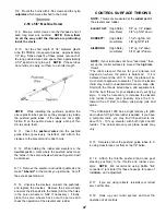
1. Make sure the control surfaces move in the proper

direction as illustrated in the following sketches:

Radio Set-Up

Four Channel Aircraft

Transmitter

Stick Movement

Control Surface

Movement

Elevator Moves Up

Right Aileron Moves
UP and Left Aileron
Moves DOWN

Rudder moves LEFT

Carburetor Wide Open

2. Adjust your pushrod hookups as necessary to

provide the proper control surface movements as
listed on Page 47

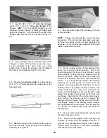
3. Check for wing twist as follows:

NOTE: Even if you have built your wing on a perfectly

flat surface and used utmost care, it is possible that
your wing may have a twist due to uneven shrinking of
the covering material You must check for this
condition and correct it before the first flight.

If you do not own a wing incidence meter, we
recommend that you purchase one from your local
hobby dealer or borrow one from another modeler.

With the wing mounted to the fuselage, use the

incidence meter to check the angle of your wing at the
root and at the tips If the incidence meter reveals a

wing twist of more than 1/4 degree, you must grasp
the wing at the tip and twist it slightly, while reheating
the covering material Keep checking, twisting and

reheating until the wing twist is removed NOTE: If

you have corrected a wing twist by this method, you
should periodically re-check to make sure the
correction has held.

PRE-FLIGHT

CHARGE THE BATTERIES

Follow the battery charging procedures in your radio
instruction manual. You should always charge your

transmitter and receiver batteries the night before you
go flying, and at other times as recommended by the

radio manufacturer.

FIND A SAFE PLACE TO FLY

1. The best place to fly your R/C model is an AMA
(Academy of Model Aeronautics) chartered club field.

Ask your hobby shop dealer if there is such a club in
your area and Join Club fields are set up for R/C
flying which makes your outing safer and more
enjoyable The AMA can also tell you the name of a
club in your area We recommend that you Join AMA
and a local club so you can have a safe place to fly
and also have insurance to cover you in case of a
flying accident (The AMA address is listed near the
front of this instruction book).

If a club and its flying site are not available,

you need to find a large, grassy area at least 6 miles
away from any other R/C radio operation like R/C

boats and R/C cars and away from houses, buildings
and streets A schoolyard may look inviting but it is

too close to people, power lines and possible radio

interference.

GROUND CHECK THE MODEL

If you are not thoroughly familiar with the operation of
R/C models, ask an experienced modeler to check to

see that you have the radio installed correctly and that

51

Содержание Ultra-Sport 1000

Страница 1: ...al assembly or material used for final assembly no liability shall be assumed nor accepted for any damage resulting from the use by the user of the final user assembled product By the act of using the...

Страница 2: ...all Servos Guide Tubes 32 Mount the Wing to the Fuse 33 Fit Fuel Tank Fuelproofing 35 Install Chin Block 35 Assemble Belly Fairing 37 Install Turtle Deck 38 Assemble Nose Section 40 FINAL ASSEMBLY 42...

Страница 3: ...table ultra smooth flying airplane that does what you want it to no more and no less Now in its largest size the Ultra Sport 1000 is better than ever The Ultra Sport 1000 is easy to build totally pred...

Страница 4: ...to check the nylon clevises and horns often and replace if they show signs of wear 6 You must fly the model only with the competent help of a highly experienced R C pilot if you are not already an ex...

Страница 5: ...The Ultra Sport 1000 may be built with a taildragger or tricycle landing gear configuration and a retractable main gear may be installed if you want to really clean up this airplane for ultra smooth...

Страница 6: ...let CA Adhesive 2 5 oz 30 Minute Bullet Epoxy Hand or Electric Drill Drill Bits 1 16 5 64 3 32 7 64 1 8 9 64 5 32 3 16 Long 13 64 1 4 and 5 16 Hobby Saw X acto Razor Saw X acto Knife 11 Blades Pliers...

Страница 7: ...7 DIE PATTERNS Use This Drawing To Identify Die Cut Parts...

Страница 8: ...to fit between the rudder framework and glue them in place NOTE It is not necessary to get these braces in the exact position shown on the plan D 4 Examine the rudder framework and add thick CA glue...

Страница 9: ...embly together D 4 From the remaining 1 4 x 1 balsa stock cut a gusset to fit in the lower front corner of the fin Glue in place IMPORTANT NOTE It is essential to get a very good glue bond between the...

Страница 10: ...y sleeve around the wire Then groove the rudder leading edge to accept the tailgear wire and the nylon tailgear bearing PARTS NEEDED TO BUILD THE ELEVATORS AND STABILIZER D 1 US10S14 3 8 x 2 3 4 x 5 B...

Страница 11: ...f the spar should line up with the lines on the plan If not sand the edges of the balsa stab center until these parts line up correctly Securely glue the stab center to the stab TE and glue the spar t...

Страница 12: ...Jig D 2 US10W15 5 16 Dia x 6 Birch Wing Dowel D 2 US10W22 Die cut 1 8 Balsa Rib 1 etc D 2 US10W27 Die cut 3 32 Balsa Ribs 4 6 13 D 2 US10W23 Die cut3 32 Balsa Ribs 3 5 D 2 US10W24 Die cut 3 32 Balsa R...

Страница 13: ...aildragger D 1 Identify the die cut 1 8 ply landing gear doublers for fixed trike gear using the following sketch D 2 The doubler for rib W 2 has a notch cut out for the landing gear block The doubler...

Страница 14: ...e 3 32 x 3 x 39 1 8 balsa sheets as shown here making four sets NOTE The two smaller front sheets will be cut on a diagonal in the next step providing you with the front pieces you will need to comple...

Страница 15: ...if any towards tip W 3 LG slots down LG doubler towards tip W 4 LG slots down LG doubler towards root W 5 Oval shaped aileron servo wire hole up W 6 Aileron servo rail slots down W 7 Aileron servo ra...

Страница 16: ...D D 11 Lightly sand the tops of the ribs to blend with the notched trailing edge then glue one of the 3 32 x 2 x 39 3 8 balsa trailing edge sheets in place NOTE The edge of the TE sheet may not be ex...

Страница 17: ...illing straight down through the middle of the 1 1 2 block D D 22 Trial fit the 3 16 diameter main landing gear wire into the landing gear block at this time Cut or file the groove and hole in the lan...

Страница 18: ...exactly where the strut socket is and make reference marks on the spar and LE so that you can later cut into the leading edge sheeting in the right place to find it after the sheeting has been instal...

Страница 19: ...the servo for servo installation and access to the mounting screws D D 38 From the 3 32 x 3 8 x 36 balsa sticks cut and glue cap strips to ribs W 5 W 8 W 9 W 10 W 11 W 12andW 13 DO NOT install the bo...

Страница 20: ...Hold the control horn in place and mark the screw locations Drill 3 32 holes for the screws drilling straight down through the aileron not perpendicular to the top or bottom surfaces Harden the balsa...

Страница 21: ...urface and block up both wing tips 1 1 2 The blocks should be located at the W 13 ribs Sand the root end of the wing panels until they fit together properly at that angle D 2 With waxed paper or prote...

Страница 22: ...up and cut a 1 2 hole in the center of the top sheeting about 1 2 behind the spars for the servo wires to exit the wing This hole should include a section of W 1 so that it provides access from one w...

Страница 23: ...er leading edge Do not attempt to wrap the glass cloth around the trailing edge D 5 Working outdoors or in a very well ventilated area apply thin CA glue to the glass cloth Begin by running a bead of...

Страница 24: ...on landing gear straps NYLON36 and temporarily install them using 2 x 3 8 sheet metal screws D 1 Mark the location of the retract servo opening as follows With the wing right side up lay a straightedg...

Страница 25: ...t fuse side to the fuse side using thick CA epoxy or aliphatic resin glue Block sand the joint smooth on both sides D 4 Carefully position the die cut 3 16 balsa lower rear fuse side so the vertical f...

Страница 26: ...the fuse plan determine which firewall A B or C is right for your engine This will govern which firewall spacers you will use For instance if your engine is an OS 120 Surpass the B firewall applies an...

Страница 27: ...crew D 1 The 3 8 firewall F 1 supplied in the kit is the D 2 The firewall drawings on the plan show the correct positioning of various J Tec engine mounts From the appropriate drawing determine the lo...

Страница 28: ...ng the other edge of the stab base Now disassemble the parts D 4 Glue the die cut 1 8 ply F 6 into the slot in the stab base F 6 must be installed in the slot as far aft as it will go and it must be p...

Страница 29: ...nd hold it securely in place with pins tape or weights or you may spray it lightly with 3M 77 spray adhesive to hold it firmly but temporarily down on the plan Note that the front edge of the fuse top...

Страница 30: ...in between When satisfied with the fit set the assembly upside down on a flat surface and check to make sure the fuse sides are vertical perpendicular to the work surface Now securely glue this aft fu...

Страница 31: ...ll the tube along the bottom of the lightening holes in the formers and exiting through the bottom sheeting a couple inches in front of the tail wedge D 14 From the 1 8 x 3 x 30 balsa sheet cut and gl...

Страница 32: ...the locations shown on the plan Temporarily mount your servos to the rails and then glue the rails to the fuse side doublers Note that the surface of the rails is even with the edge of the lightening...

Страница 33: ...ar strut and file a notch in the strut at the setscrew location This will prevent the strut from slipping under high stress Leave the steering arm and pushrod in place D 12 With the engine resting on...

Страница 34: ...ou will get erroneous incidence readings If you are working on a flat surface that is not level you must set the wing incidence the same as your flat surface D 5 After making the necessary corrections...

Страница 35: ...the nose gear If you do it now it will be easier to feed the fuel lines through F 1 and to make sure there are no kinks in the lines however you ll have to work around them while completing the nose I...

Страница 36: ...here the front of F 1 intersects the chin block D 4 Fuelproof the portion of the chin block that will become the inside floor of the fuel tank compartment Note that we have also installed a dribble tu...

Страница 37: ...sing scrap 1 16 balsa or plywood as temporary spacers to separate these formers from the fuselage formers Sand the bottom edges of these formers to the angle of the wing surface Also sand them down un...

Страница 38: ...ightweight balsa filler and make nice fillets between the belly fairing sides and the bottom wing sheeting INSTALL TURTLE DECK PARTS NEEDED D 1 US10F27 1 8 Die cut Ply Formers F 3A F 4A and F 5A D 1 U...

Страница 39: ...k D 8 Wet the outside surface of the sheeting with a damp rag to permit easier bending Pull in the sheeting against the formers and stringers using approximately 10 long pieces of masking tape as show...

Страница 40: ...k D 1 Find the 1 4 x 5 16 x 11 balsa cockpit sides Cut off one end of each stick at an angle to fit the front edge of the backrest F 3A The cockpit sides are 5 16 tall and 1 4 wide D 2 Glue the cockpi...

Страница 41: ...ve a groove for the needle valve Cut and sand off the front of the top front block to mate with the spinner ring The top front block should overlap the spinner ring approximately the same amount as th...

Страница 42: ...nd 1 2 balsa triangle cut pieces to partially fill in the right side around the engine The right cowl side should be essentially the same as the left side with the exception of the engine cutout Also...

Страница 43: ...LETS OPTIONAL PARTS NEEDED D 1 US10F36 Die cut 1 32 ply Wing Fillet Bases Filler or scrap soft balsa see below NOTE The wing fillets are a nice addition to the US1000 They make it more pleasing to the...

Страница 44: ...in Fairings D 1 Using only one or two small drops of glue on each piece tack glue the following balsa parts together see sketch Method 2 Apply a good quality lightweight model filler light spackle sha...

Страница 45: ...UNT STABILIZER AND FIN PARTS NEEDED D 1 US1 0F15 1 2 x3 4 x1 5 8 Balsa Stab Filler Block D 1 WSHR012 3 4 Flat Washer D 1 SCRW070 8x1 Sheet Metal Screw D 1 US10F07 1 2 x30 Hard Balsa Triangle Stock D 1...

Страница 46: ...les in the servo arms Remove the pushrods and make a Z bend in each rod at that point using a Z bend pliers or a standard pliers Cut off the excess pushrod wire D 4 Remove the servo wheel from the ser...

Страница 47: ...ll be much more responsive to elevator Too much elevator throw may result in unwanted stalls or even snap rolls Start with the throws listed above and experiment to find the best throws for your airpl...

Страница 48: ...for trimming the canopy NOTE The trim line on the canopy is approximate Your canopy trim will vary depending on how you sanded the fuselage It may be necessary to do some additional sanding of the fu...

Страница 49: ...X acto knife to cut slits in the covering at the hinge locations Trial fit the hinges to make sure you have found the slots which you previously cut 2 If you have built a taildragger glue the tailgea...

Страница 50: ...ay the wing in the saddle and push down gently The excess silicone sealer will squeeze out 4 Allow to dry without disturbing for at least 24 hours 5 Remove the tape then remove the wing from the saddl...

Страница 51: ...t you purchase one from your local hobby dealer or borrow one from another modeler With the wing mounted to the fuselage use the incidence meter to check the angle of your wing at the root and at the...

Страница 52: ...et into the running propeller Use a low throttle setting when starting the engine Make all engine adjustments from behind the rotating propeller The engine gets hot Do not touch it during or after ope...

Страница 53: ...ndled the way the guy who designed it thought it should If your model s wing has a degree more or less of incidence then the whole balance formula is incorrect for you But it s a good ballpark place t...

Страница 54: ...tic changes glance at the remainder of the chart and note the many combination of things we can do just with the ailerons Each change you make will affect all other variables Note that the Yaw test is...

Страница 55: ...ted D Plane goes out on both types of loops E Plane goes in on both types of loops A Wings are level throughout B Yaws to right in both inside and outside loops C Yaws to left in both inside and outsi...

Страница 56: ...al Communications Commission IMAA SAFETY GUIDELINES As of September 15 1989 Portions reprinted as follows For the purpose of the following IMAA Safety Guidelines the term Giant Scale refers to a radio...

Страница 57: ...57...

Страница 58: ...s front mounted engine and prop offer familiar sport model construction The speed you need to turn and burn The speed and maneuverability of ducted fan jets in an easy to fly affordable sport design...

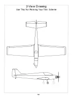
Страница 59: ...2 View Drawing Use This For Planning Your Trim Scheme 59...

Отзывы: