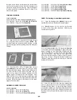
D 6. Now center your spinner backplate over the
spinner ring, and tack glue it to the 3/32" balsa
spacers.
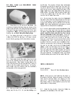
D 7. Slide the spinner ring / spinner backplate
assembly onto the driveshaft* and temporarily hold in
place with the prop and prop nut. As you are doing
this, shorten the chin block by trial and error until the
spinner ring just touches the chin block when the
backplate is tightened against the engine. In this
position, the spinner ring should overlap the front edge
of the chin block by approximately 3/8" to 1/2". Now
glue the spinner ring to the chin block.
*NOTE: If you are using a SuperTigre 2500 engine,
you will either have to drill two 5/32" holes in the
spinner backplate or grind off the two conical points on
the engine's thrust washer.
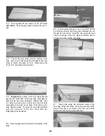
D 9. Lay the top front block in place on top of the
fuselage. The aft end of the block should be in the
position shown on the plans (measure forward from F-
3A). Depending on your engine, you may also have to
carve a groove for the needle valve. Cut and sand off
the front of the top front block to mate with the spinner
ring. The top front block should overlap the spinner
ring approximately the same amount as the chin block,
and you may re-sand (or shim) the angle on the
cockpit sides to achieve this overlap. In addition,
check if your engine mount touches the top front
block, and provide clearance as necessary. Glue the
top front block to the fuse and the spinner ring, using
epoxy on the joint between the firewall and the top
front block.
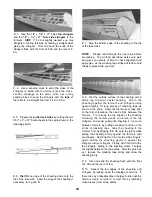
D 10. Cut two 2-1/2" lengths from the 3/8" balsa
triangle stock and shape them to fit under the top front
block, just in front of the instrument panel. Glue in
place.
D 8. Glue together the two halves of the 3/4" balsa
top front block. Sand the glue joints smooth with
your T-bar. Using the fuse plan side view as a guide,
mark and cut off the aft edge of the top front block to
the angle shown at the instrument panel.
D 11. Sand the sides of the die-cut 3/32" balsa
instrument panel to fit between the cockpit sides, and
sand the bottom edge to an angle so it rests flat on the
cockpit floor. Glue the instrument panel in place.
41
Содержание Ultra-Sport 1000
Страница 7: ...7 DIE PATTERNS Use This Drawing To Identify Die Cut Parts...
Страница 57: ...57...
Страница 59: ...2 View Drawing Use This For Planning Your Trim Scheme 59...


