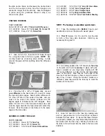
D 7 Cut off the tubes at the exit points and sand
them flush with the fuse sides using a sanding block.
STEPS 8 - 1 1 ARE FOR TRIKE GEAR ONLY
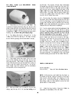
D 8. Temporarily install the nosegear and nosegear
steering arm if you are building a tricycle
configuration If there is any possibility of the steering
arm binding against the engine mounting hardware,
cut 1/4" off the end of the steering arm Cut a 12"
length from the remaining outer pushrod guide tubing
and use it for the nosegear pushrod guide.
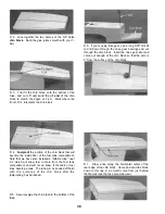
D 9 Route the nosegear steering pushrod from the
rudder servo arm to the steering arm, anchoring the
outer guide tube to formers F-2 and F-3.
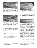
D 10 Hook up the pushrod to the steering arm (using
a nylon clevis) and to the servo arm (using an EZ
Connector) Rotate the servo arm to its neutral
position, and set the nosegear to neutral Rotate the
steering arm away from the firewall to provide
sufficient free movement With the components in
position as described above, tighten the steering arm
set screw onto the nosegear strut which will mark the
strut for the next step.
D 11 Remove the nosegear strut and file a notch in
the strut at the setscrew location This will prevent the
strut from slipping under high stress Leave the
steering arm and pushrod in place
D 12 With the engine resting on the mount, plan the
throttle pushrod routing The pushrod should be
located as close as possible to the fuse side (to allow
room for the fuel tank), and the guide tube should not
have any tight bends Drill a 3/16" hole in F-1 for the
throttle pushrod guide tube.
D 13. Drill or carve holes in F-2 and F-3 for the guide
tubes Cut the remaining pushrod guide tube to length
and trial fit the tube in the fuselage Glue the tube in
place, then trim and sand the tube flush with the front
of F-1.
D 14 Cut the pushrod wire to the required length
and temporarily install the throttle pushrod Use the
nylon clevis (NYLON 17) if needed for attachment of
the pushrod to the engine throttle arm ______
D 15 Now remove the pushrod wires, engine, engine
mount and servos (Leave the nosegear steering
pushrod in place.
MOUNT THE WING TO THE FUSE
PARTS NEEDED:
D (2) NYLON 13 1/4-20 Nylon Bolts
D 1. Sand the top surface of the fuse to remove any
excess glue so the fuse will lie flat on the workbench
D 2 Sand the entire wing saddle area lightly until the
fuse side doublers and fuse sides are flush.
33
Содержание Ultra-Sport 1000
Страница 7: ...7 DIE PATTERNS Use This Drawing To Identify Die Cut Parts...
Страница 57: ...57...
Страница 59: ...2 View Drawing Use This For Planning Your Trim Scheme 59...


