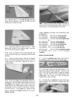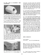
Slightly round (or chamfer) the ends of the dowels that
will protrude out of the LE
INSTALL RETRACT SERVO
(Skip this section if you are using fixed gear)
D 6 Trial fit the dowels into the dowel holes You
should be able to probe around and find the dowel
holes in the dihedral brace Now trial fit the dowel
plate over the dowels If the dowels fit too tightly, you
may enlarge the holes slightly using a round file
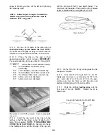
D 7. Mix up a batch of 30-minute epoxy Use a long
stick to work some epoxy into the dowel holes Smear
epoxy on the dowels and then re-insert the dowels
into the wing leaving them protrude 1/2" Wipe away
all excess epoxy Then allow the epoxy to fully
harden
INSTALL WING BOLT PLATE
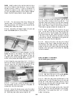
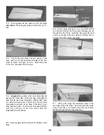
D 1 Mark a centerline on the die-cut 1/16" x 4-1/2" x
2-1/4" ply wing bolt plate.
D 2 Position the wing bolt plate on the bottom of the
wing, with the punch marks visible, and line it up
with the wing TE and centerline Glue it in place
D 3 Sand the wing bolt plate flush with the wing TE.
FILL LANDING GEAR SLOTS
(For fixed gear only)
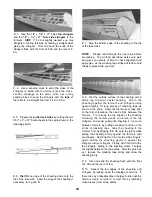
D 1. Temporarily install the main LG wires.
D 2 Check the plan for the location of the nylon
landing gear straps (NYLON36) and temporarily install
them. using #2 x 3/8" sheet metal screws
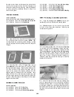
D 1 Mark the location of the retract servo opening as
follows With the wing right side up lay a straightedge
along the aft edge of the spars and draw a reference
line on the fiberglass cloth From this line, measure
forward and make marks at 1-5/8" and 2-7/8 Draw
lines through these marks and parallel with the
reference line Now measure and make marks 1-1/8"
left and right of the wing centerline and draw lines
through these marks and parallel with the wing
centerline
D 2 Cut a hole in the top sheeting for the retract
servo installation
D 3 Working through this hole cut away as much of
the W-1 ribs as necessary to permit the die-cut 1/8"
ply retract servo tray to rest down on top of the 5/16"
dowels and to provide clearance for the retract servo
itself Now securely glue (epoxy is recommended) the
servo tray to the top of the wing dowels Enlarge the
hole if necessary to perform this installation, but keep
it as small as possible
D 3 Using scraps of balsa, fill the ends of the slots in
the notched LG blocks and sand flush with the surface
of the wing This will aid in covering later
D 4 Install your retract servo hook up the retract
pushrods and make a final check that everything is
working properly
24
Содержание Ultra-Sport 1000
Страница 7: ...7 DIE PATTERNS Use This Drawing To Identify Die Cut Parts...
Страница 57: ...57...
Страница 59: ...2 View Drawing Use This For Planning Your Trim Scheme 59...

