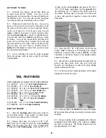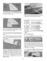
D 4 Using a sanding block and coarse (50 or 80-grit)
sandpaper, sand both sides of the elevators to a taper
as shown on the plans. The trailing edge should end
up approximately 1/16" wide. (See photo proceeding
page.)
D 5 Select the two softest (lightest) 1/16" x 3" x 30"
balsa sheets, and use them to sheet both sides of the
elevators Make sure you obtain a good glue bond
between the sheeting and the internal structure.
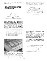
D 6. Sand the leading edge of the elevators to a "V-
shape" as shown on the plan Sand the trailing edge
to a slightly rounded shape Do not round the elevator
ends (leave them square)
between the stab sheeting and the stab
framework, especially in the center, therefore, we
recommend using 30-minute epoxy when you apply
the final piece of sheeting Spread the epoxy evenly
but sparingly, to avoid excess weight
D 6 Cut one end of the two 1/2" x 2" x 14-7/8" balsa
stab leading edges to match the plan at the stab
centerline Glue the leading edges to the stab
framework Cut and sand the ends of the leading
edges to match the ends of the stab.
D 7 Glue the 1/2" x 1" x 6-1/4" balsa stab tips to the
ends of the stab Trim and sand the front ends of the
stab tips to match the plan
BUILD THE STABILIZER
NOTE: You will construct the stab framework and
add the 1/16" balsa sheeting, then, you will add the
1/2" balsa leading edges and tips.
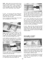
D 1 Accurately pin the 3/8" x 3/4" x 26-3/4" balsa
stab TE onto the plan.
D 8 Temporarily tape the elevators to the stab.
While holding the elevators in the neutral position,
sand the 1/2" x 1" stab tips to match the elevator.
D 2 Trial fit the 3/8" x 2-3/4" x 5" balsa stab center
and the triangle-shaped 3/8" ply spar* in place on the
plan. The leading edge of the spar should line up with
the lines on the plan If not, sand the edges of the
balsa stab center until these parts line up correctly
Securely glue the stab center to the stab TE, and glue
the spar to the stab center.
*NOTE: It is common for the 3/8" ply to be slightly
thinner than the 3/8" balsa For this reason, we have
included a 1/32" x 1-1/4" x 11-1/2" ply sheet If the
spar in your kit is thinner than the 3/8" balsa stab
center, glue the 1/32" ply sheet to the spar, and trim
the edges to match the spar.
D 3 Complete the stab framework by cutting and
fitting pieces of 1/8" x 3/8" x 30" balsa, as shown on
the plan. Glue this assembly together.
D 4 Remove the stab framework from the building
board and sand both sides and all edges smooth.
D 5. There are four remaining 1/16" x 3" x 30" balsa
sheets Edge glue these sheets together in pairs to
make two 6" x 30" sheets, and sand both sides
smooth with a sanding block Use these to sheet the
top and bottom of the stab framework NOTE: It is
essential to get a strong and complete bond
D 9 Draw a centerline on the stab leading edge and
tips, which will help to maintain symmetry while
sanding.
D 10. Using a sanding block, sand the stab leading
edge to the approximate shape as shown in the stab
cross-section on the plan Sand the stab tips to a
rounded shape.
TEMPORARILY INSTALL HINGES
D 1 Using the plans as a guide, mark the hinge
locations on the stab, elevators, fin and rudder.
NOTE: There are many types of good hinges on the
market, and everyone has their personal preferences,
therefore, hinges have not been included in this kit.
The current favorite for many modelers is the type of
laminated hinge that permits hinge slotting with an
X-acto knife, and gluing with thin CA adhesive If you
are building a taildragger, heavy-duty hinges are
recommended for the rudder See the IMAA Safety
Guidelines in the Appendix at the end of this book.
11
Содержание Ultra-Sport 1000
Страница 7: ...7 DIE PATTERNS Use This Drawing To Identify Die Cut Parts...
Страница 57: ...57...
Страница 59: ...2 View Drawing Use This For Planning Your Trim Scheme 59...

