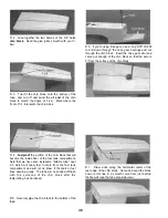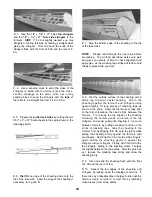
correct size for the "A" firewall location (see Engine
Application Table). If your engine requires the "B" or
"C" firewall, it is necessary to cut the firewall down to
the proper size Drawings for all three firewalls are
shown on the fuse plan. Use these drawings to
determine how much to cut NOTE: The top and
bottom edges of F-1 are beveled at an 8-1/2 degree
angle. When you cut your firewall, be sure to maintain
the same angles on these edges Mark the "Front"
and "Top" of F-1 for future reference.
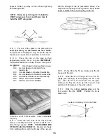
For the "B" firewall location, glue spacer "BL" to the
left side and "BR" to the right side.
For the "A" firewall location, glue the 1/8" x 3/16" x
4-1/4" hardwood stick (part #US10F08) to the left
side (the top edge of the stick must be flush with the
top edge of the slot in the doubler), and do not
install any spacer on the right side.
PREPARE THE FIREWALL (F-1)
PARTS NEEDED:
D (1) US10F05 3/8" x 4-7/16" x 4-5/16" Ply Firewall (F-1)
D (1) Set Engine mount & hardware to f i t your
engine (see Engine Application Table)
(NOT INCLUDED)
ADDITIONAL PARTS REQUIRED FOR TRIKE GEAR:
D (1) WBNT169 3/16" Wire Nose Gear Strut
D (2) NYLON05 Nylon Nose Gear Bearings
D (4) NUTS001 4-40 Blind Nuts
D (4) SCRW036 4-40 x 3/4" Machine Screw
D (1) NYLON69 Steering Arm for 3/16" Wire
D (1) SCRW007 6-32 x 1/4" Socket Head Cap Screw
D (2) WHCL011 3/16" Wheel Collars
D (2) SCRW005 6-32 x 1/8" Set Screw
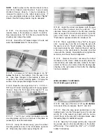
D 1. The 3/8" firewall (F-1) supplied in the kit is the
D 2. The firewall drawings on the plan show the
correct positioning of various J-Tec engine mounts.
From the appropriate drawing, determine the location
of your mount on your firewall Note that the mount
should be located slightly off center because of the 2
degrees of right thrust Place your mount on the
firewall and mark the location of the mounting holes.
NOTE: Hole locations may vary from mount to
mount, so do not drill the holes based on the drawing .
. . use your actual mount to locate the holes.
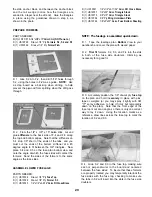
D 3. Drill holes in F-1 for your engine mount J-Tec
"SV" (rubber isolated) mounts are shown on the plan,
and are recommended for this model, and they require
you to drill 3/8" diameter holes To drill the holes
accurately, we recommend first drilling a 1/8" pilot
hole, followed by a 1/4" hole, then drill the 3/8" holes.
If you choose to use a non-isolated mount, drill the
holes to fit 10-32 bolts and blind nuts.
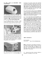
D 4. The firewall drawings also show the
recommended position of the nylon nose gear
bearings If you are building a tnke gear version, use
the drawing to determine the location of these nylon
bearings, and mark the mounting hole locations Drill
9/64" holes for the 4-40 bolts and blind nuts The blind
nuts will be installed on the front of the firewall, so it
may be necessary to countersink one or more of them
to permit the engine mount to rest flat on the firewall.
NOTE: It is also necessary to drill out the nylon
bearings to accept the 3/16" nose gear strut.
27
Содержание Ultra-Sport 1000
Страница 7: ...7 DIE PATTERNS Use This Drawing To Identify Die Cut Parts...
Страница 57: ...57...
Страница 59: ...2 View Drawing Use This For Planning Your Trim Scheme 59...


