


COVERING
NOTE: Top Flite Super MonoKote was used to
cover and trim the prototype models of the Ultra-
Sport 1000, and that is the recommended covering
for this model.
Because it is assumed that you have had
some previous model building experience, we won't
go into detail in regard to the covering procedure.
Follow the instructions included with your
covering material.
NOTE: When covering the fin and stab, begin by
applying 1/2" wide strips of covering in the corners
between the fin and the fairing block, between the stab
and the fairing block, and (on the bottom of the stab)
between the stab and the fuse sides Next cover the
fairing blocks with pre-cut pieces of covering Finally,
cover the stab and fin with pre-cut pieces that have a
straight edge to overlap (1/8"+ overlap) the strips you
p r e v i o u s l y applied DO NOT, under any
circumstances, attempt to cut the covering
material after it has been applied to the fin and
stab, except around the leading and trailing edges
and the tip. Modelers who do this often cut through
the covering and part-way into the balsa stab This
can weaken the stab to the point where it may fail in
flight'
Recommended Covering Sequence:
1. Strips as described in above note
2. Rudder left side
3. Rudder right side
4. Bottom of elevators
5. Top of elevators
6. Stab bottom
7. Stab top
8. Fuse bottom
9. Wing fillets*
10. Fuse sides
11. Fuse top
12. Fin left side
13. Fin right side
14. Ends of ailerons
15. Bottom of ailerons
16. Top of ailerons
17. Aileron openings in wing
18. Wing fairings (on bottom of wing)
19. Bottom of left wing panel
20. Bottom of right wing panel
21. Top of left wing panel (overlap covering 1/4" at
wing LE)
22. Top of right wing panel (overlap covering 1/2"
at the center and 1/4" at the LE)
*When covering concave surfaces, such as the wing
fillets, use a Top Flite "Trim Seal Iron" with the
rounded tip, and follow the iron with a damp cloth,
pressing the covering down.
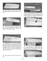
GLUE THE HINGES
1 Lay the rudder, elevators and ailerons on the plans
and mark on the leading edge of each part the
locations of the hinges (and tailgear if you have built a
taildragger) Now use a sharp X-acto knife to cut slits
in the covering at the hinge locations Trial fit the
hinges to make sure you have "found" the slots which
you previously cut.
2. If you have built a taildragger, glue the tailgear
bearing into the slot in the aft end of the fuse, using
the following procedure Using a toothpick, apply a
small amount of Vaseline where the tailgear wire
enters the nylon bearing (to prevent glue from getting
inside and locking it up) When gluing in the nylon
tailgear bearing, do not just smear glue on the nylon
and push it into the slot as most of the glue will be
wiped off as it is being pushed in You must also work
some glue into the slot A good way of doing this is to
scoop up some epoxy with a plastic soda straw, then
pinch the end of the straw, insert it into the slot, and
squeeze the straw to force glue into the slot Apply
epoxy to the nylon, then insert it into the slot We
recommend 30 minute epoxy for this process After
pushing in the nylon bearing, wipe away all excess
glue with a tissue dampened with rubbing alcohol.
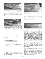
3. If you are using the type of laminated hinges that
are installed with thin CA glue merely assemble the
ailerons to the wing and the elevators to the stab with
dry hinges, check alignment, and then apply several
drops of thin CA to both sides of each hinge You
should keep a tissue handy while doing this, to soak
up any excess CA in the event that you notice it
starting to run down the hinge line
4. If you have built a taildragger, the procedure for
hinging the rudder is slightly different Using coarse
sandpaper, roughen the part of the tailgear wire that
will be glued into the rudder, then clean off the sanded
portion of the wire with alcohol or a degreasing
solvent Put epoxy into the tailgear hole in the rudder,
push the rudder and hinges into place and wipe off all
excess epoxy Check the vertical positioning of the
rudder, and glue the hinges securely in place with thin
CA.
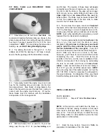
INSTALL PILOT
1 Assemble your pilot figure and trial fit it into the
cockpit area with the canopy in place If you are using
the recommended Williams Bros 1/4-scale pilot, you'll
probably have to cut it down to fit If you cut it down,
you should cut a new pilot base from scrap 1/8" ply,
and glue it securely inside the pilot figure in
preparation for the next step
49
Содержание Ultra-Sport 1000
Страница 7: ...7 DIE PATTERNS Use This Drawing To Identify Die Cut Parts...
Страница 57: ...57...
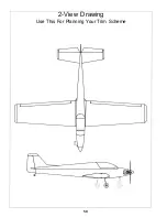
Страница 59: ...2 View Drawing Use This For Planning Your Trim Scheme 59...


