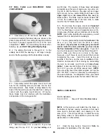
D 3. Apply a few strips of masking tape to the turtle
deck for protection, then carve and sand the above
assembly to blend smoothly with the fuse sides and
the turtle deck.
D 4. Break the assembly off the stab saddle and cut
the parts apart. Save the shaped fin fairings for later.
D 5. Lay the stab in position on the stab saddle with
the center point lined up with the tail end of the
fuselage. If the stab protrudes beyond the end of the
fuselage, sand a little off the front of the stab until it
fits Carefully check the stab alignment by looking at
the stab and wing from directly behind the fuse . .. the
stab must be parallel with the wing Also check for
stab skew by measuring from the stab tips to the wing
tips (or to a point on the center of the fuse near the
nose) Sand the stab saddle (a little at a time!) until
the stab rests in proper alignment. With the stab in
alignment, make a mark on the front of the stab and a
corresponding mark on the back of F-6A, which will be
used for rapid alignment when gluing.
D 6. Mix up a batch of 5-minute or 30-minute epoxy
and apply it to the stab saddle Press the stab into
position and hold or pin in proper alignment until
the glue has firmly set Wipe off any excess epoxy
before it sets up.
MOUNT STABILIZER AND FIN
PARTS NEEDED:
D (1) US1 0F15 1/2"x3/4"x1 -5/8" Balsa Stab Filler Block
D (1) WSHR012 3/4" Flat Washer
D (1) SCRW070 #8x1" Sheet Metal Screw
D (1) US10F07 1/2"x30" Hard Balsa Triangle Stock
D (1) US10S19 Shaped 3/8" Balsa Dorsal Fin
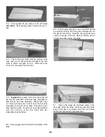
D 1. Make sure the stab base is securely glued to the
fuse sides, then lightly sand the stab saddle area
smooth with a T-bar or sanding block.
D 2. Find the 1/2" x 3/4" x 1-5/8" balsa stab filler
block and glue it to the stab saddle and the back of F-
6A. Sand off the ends flush with the fuse sides.
D 3. Accurately measure the trailing edge of the
stabilizer and mark the center point Draw a centerline
on the top of the stab Measure 4-1/8" forward, along
the centerline, from the stab TE and drill a 5/32" hole
down through the stab This will be the location of the
stab locking screw. (See the photo at Step 7).
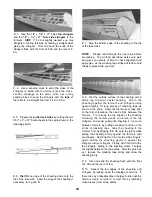
D 4 Temporarily mount the wing in the saddle (for
reference).
D 7 Insert a 1/8" drill into the hole you previously
drilled in the stab, and drill down through the stab
base and stab hold-down block in the fuse Put the
large washer onto the # 8 x 1 " sheet metal screw,
apply epoxy to the screw threads, and tighten the
screw down onto the stab
D 8 Trial fit the fin onto the stab The fin trailing
edge must line up with the aft end of the fuselage. If
the fin protrudes too far aft, sand a small amount off
the front of the fin Remove material from the bottom
of the fin to clear the screw and washer.
45
Содержание Ultra-Sport 1000
Страница 7: ...7 DIE PATTERNS Use This Drawing To Identify Die Cut Parts...
Страница 57: ...57...
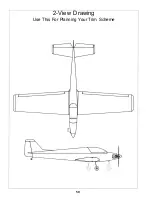
Страница 59: ...2 View Drawing Use This For Planning Your Trim Scheme 59...


