background image

We used and recommend the Hitec

HS-55 Feather Servos for

this model. Of course you can use different brands of servos but
make sure they are the same size, weight, and output as the 
HS-55 units.
IMPORTANT SERVO NOTE: The Hitec

HS-55 servos we used

in this kit all had off-the-shelf servo lead lengths of 10-1/2". This
meant that we did not have to add servo extensions to these 
servos to reach the center of the wing. If you are using servos with
shorter leads, you will likely have to add servo lead extensions.

For receivers, we have used the Hitec

#555, the Hitec

Electron

6 and the FMA M5 units. All three of these receivers are dual 
conversion types. These receivers are light, have excellent range
and, because they are dual conversion types, they are perfect for
use at any typical R/C flying field. We do not recommend using 
single conversion receivers for this model.

We used a Hitec

270 mAh NiCad airborne battery pack for our

Little Extra models. In actual use, we found that after being fully
charged, we could fly for an honest 40 minutes or so before 
needing to be recharged. The Y-harness is used to join the two
aileron servos and the 6" servo extension is required to connect
the ailerons to the receiver. We used the small Hitec

On/Off

switch assembly in the interest of weight and size.

Finally, the transmitter you use for this model is important. For our
Little Extra ARF models, we used both the Hitec

Flash 4 and the

Airtronics

®

RD-6000 transmitters.

Both of these affordable 

systems offer multi-model memory and a host of easy-to-use 
computer features that make radio set-up and flying a whole 
easier and much more fun. If you do not use these transmitters or
similar units, the set-up and flying of your model is going to be
more difficult.

ENGINE SELECTION:

As previously mentioned, the Little Extra ARF was specifically
designed to fly very nicely using the Norvel

.074 BigMig R/C

engine. The use of this recommended engine provides really 

1

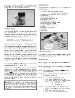
INTRODUCTION
Congratulations on the purchase of the HERR ENGINEERING
Little Extra ARF kit!  The Little Extra is one of the first true high 
performance 1/2A fun-fly R/C type models to be available in an
Almost Ready to Fly format. Like larger fun-fly type sport models,
the Little Extra is loaded with a lot of features and truly 
exhilarating performance potential.

The airframe is very light,

beautifully built and engineered to last a long time. The covering
has been professionally applied and the trim scheme is just about
perfect for this type of model. The assembly process is very quick
and further enhanced by the completeness of the kit.

Properly powered and flown, the Little Extra is a very capable 
fun-fly type model!  The airplane itself has been specifically
designed around the powerful little Norvel .074 BigMig R/C
engine. The kit includes a custom-cut motor mount assembly
specifically for this engine and even includes a custom aluminum
spinner insert for the spinner, designed to fit the .074 prop shaft.
In the air you will find it hard to believe that such a small model can
fly so "big". The Little Extra is fully capable of just about any R/C
maneuver you care to throw at it - point rolls, snaps, knife-edge,
inverted flight, lomcevaks, etc.

Who knew flying small gas 

powered models could be so fun!  Herr Engineering, that’s who.

To take full advantage of the Little Extra’s potential flight envelope,
we urge you to carefully review this Assembly Manual, paying 
particular attention to the radio and battery equipment 
suggestions.

These suggestions are based upon a lot of 

experience with this design and should be heeded. The success
of this model is based upon its light ready-to-fly weight, so you
want to be sure your airborne equipment is as light as possible.

Finally, the Little Extra ARF design is not intended as a beginner's
R/C model. The design assumes that you are a proficient R/C
pilot, capable of flying relatively high-performance model aircraft.

RADIO EQUIPMENT

As mentioned previously, it is very important to select the correct
airborne radio equipment for your Little Extra ARF model. This
Assembly Manual will show the use of the following equipment.
This equipment is what we have used and can highly recommend
for the Little Extra ARF:

5 Micro Servos 

(Hitec

HS-55 Servos used, (Hitec

P/N 31055*)

1 Micro Receiver 

(see suggested receivers below)

1 270-300 mAh Airborne Battery Pack 

(Hitec

P/N 57405*)

1 Hitec

Miniature Switch Harness 

(Hitec

P/N 54403*)

1 Hitec

6" Y-Harness 

(Hitec

P/N 57351*)

1 Hitec

6" Servo Extension 

(Hitec

P/N 57344*)

(*With these part numbers you must specify the connector type for your radio system)

Содержание little extra

Страница 1: ...ger fun fly type sport models the Little Extra is loaded with a lot of features and truly exhilarating performance potential The airframe is very light beautifully built and engineered to last a long time The covering has been professionally applied and the trim scheme is just about perfect for this type of model The assembly process is very quick and further enhanced by the completeness of the ki...

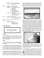
Страница 2: ...h the iron when working around any seams Overheating a seam may cause the covering to creep exposing the wood beneath Also use caution when working with heat around the canopy area heat will distort this clear plastic material REQUIRED TOOLS For proper assembly we suggest you have the following tools and materials available A selection of glues SIG Thin and Thick CA and SIG Kwik Set 5 Minute Epoxy...

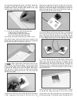
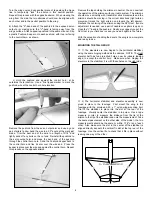
Страница 3: ...the pre cut hinge slots in the wing panel up to the hinge slot cut out Place a card wedge into each hinge center and then press the aileron in place onto each exposed hinge half up to the card wedges Align the outer tip of the aileron with the wing panel tip The hinges are now in proper position for permanently gluing in place with thin CA glue Flex the aileron downward about 30O or so exposing bo...

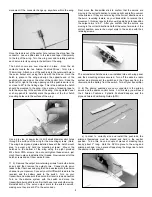
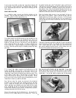
Страница 4: ...ply some thick CA glue to one end of one of the hardwood mounting blocks and press it in place next to the servo beneath its mounting lug and use CA accelerator to set the glue Apply glue to the end of another mounting block and press it in place on the opposite side of the servo beneath the mounting lug Remove the tape and the remove the servo Use a small diameter drill to make pilot holes in the...

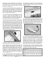
Страница 5: ...o leads to the Y harness and plug the Y harness lead into the aileron channel in your receiver Connect your On Off switch lead into the receiver and the battery pack to the switch Turn on your transmitter and make sure the aileron trim lever is in dead neutral Turn on the airborne system with the switch and move the transmitter aileron stick to confirm that he servos are both moving Reinstall both...

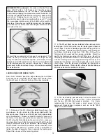
Страница 6: ...measurement on the other side of the model the two measurements should be the same or within 1 16 or so of each other Also make sure the slot in the center of the stabilizer is aligned directly beneath the vertical fin slot at the top rear of the fuselage Use the vertical fin to check that it fits in place without leaning one way or the other Turn the wing over and use another piece of tape along ...

Страница 7: ...tabilizer elevator assembly carefully back in place into the fuselage Once again align the stabilizer squarely to the fuselage per the above instructions With everything aligned set the model on a flat surface and stand back a few feet to view it directly from the front The stabilizer should be parallel with the wing in front view If it is tilting one way or the other use tape or small weights to ...

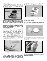
Страница 8: ...ct or small diameter drill bit to clear out this hole to allow clearance for the rudder control horn mounting spikes 6 The tail wheel mounting plate is now secured to the bottom rear of the fuselage with the two M2 x 6mm PWA screws included with the tail wheel assembly Slide the mounting bracket up to the fuselage and hold it centered in place to the bottom of the fuselage Use a marking pen or poi...

Страница 9: ...front guide the tank through the fuselage wing saddle and into the tank former Continue pulling the string until the stopper assembly fits into the round cut out in the front face of the firewall From the rear push the tank firmly into position as far forward as it will go The silicon sealer will form a very nice gasket protecting the inside of the fuselage from fuel 2 The balsa Fuel Tank Retainer...

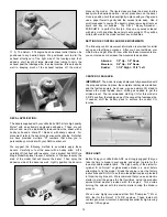
Страница 10: ... radio system RADIO INSTALLATION 1 Install the rudder elevator and throttle pushrods into the fuselage From the open wing saddle insert the unbent ends of each wire pushrod into the appropriate tubes The rudder elevator and throttle servos are now installed onto the fuselage servo tray as shown We installed the rear rudder and elevator servos first and the throttle servo last We also found it help...

Страница 11: ...g tape to hold the elevators in neutral to the horizontal stabilizer Turn the transmitter on followed by the airborne radio system Make sure the transmitter elevator trim is in neutral Turn the fuselage over for easy access to the bottom of the horizontal stabilizer Slide one of the plastic pushrod keepers in place onto the pushrod with its arm facing to the rear and move it back toward the fusela...

Страница 12: ...n place Thread one of the M3 Hex Nuts in place almost up to the wheel hub Thread a second M3 Hex Nut in place up to the first nut Use pliers or a metric box end wrench to hold one of the M3 nuts while firmly tightening the second nut to it make sure the wheel turns freely Slide the exposed end of the M3 Axle Bolt through the bottom hole in the aluminum Main Landing Gear Start to thread one of the ...

Страница 13: ...n even lower idle speed can be obtained However you must experiment a little to obtain the lowest possible reliable idle speed without killing the engine Our experience with this simple modification has given us very reliable low speed idle characteristics and after adjusting the trims on our transmitter even the ability to use the Throttle Cut feature available with some transmitters 2 Now is the...

Страница 14: ... engines makes break in a must before attempting to fly the model Break the engine in per the factory instructions and DO NOT use the molded plastic spinner provided in this kit during break in We recommend that you use an electric starter to start the engine the first few times using the propeller spinner thrust washer provided with the engine This avoids burning the spinner with the electric sta...

Страница 15: ...this model Such conditions are always best for evaluating and trimming R C aircraft especially smaller models We also strongly suggest that you perform a complete range check of your radio system with and without the engine running Radio system problems will not magically disappear once you re in the air We suggest that you take this model off from the ground Rise Off Ground While it might be poss...

Страница 16: ...16 HERR LITTLE EXTRA LOG BOOK Date of first flight Comments ...

Отзывы: