


3
4
M2.6 x 12mm PWA Engine Mounting Screws
1
Sub Bag (a)
8
M2 x 5mm PWA Aileron Hatch
Cover Screws
Bag #7
1
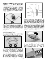
Pre-Bent Aluminum Main Landing Gear
1
Sub Bag (a)
2
2" Dia. Main Wheels
1
Sub Bag (b)
2
M3 x 25mm Wheel Axle Bolts
4
M3 Hex Nuts
2
M3 Lock Nuts
4
M3 Flat Washers
2
9mm PWA Screws
2
M3 x 10mm PWA Bolts
2
M3 Split Ring Lock Washers
1
Sub Bag (c)
1
Tail Wheel Wire
1
Brass Tail Wheel Mounting Bracket
2
M2 x 6mm PWA Screws
1
15mm Dia. Tail Wheel
Bag #8
1
1-1/2" Dia. SIG Spinner Assembly
1
Sub Bag (a)
2
2.6mm x 10mm Assembly Screws
1
4mm Prop Shaft Adaptor
(Norvel
™
.074)
Bag #9
2 Wheel Pants, 1 Left, 1 Right, Factory Painted
Bag #10
1 Fuel Tank Assembly
1
Sub Bag (a)
1
Metal Clunk
3
Metal Fuel Tank Lines
1
Rubber Tank Stopper
With Mounting Hardware
Little Extra Decal Sheet
Little Extra Assembly Manual
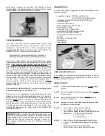
ASSEMBLY:
To avoid unnecessary "dings", dents, or scratches, we suggest
covering your workbench with a sheet of light foam or an old
blanket to protect the pre-covered parts. We also suggest that you
fully charge the transmitter and airborne battery pack for use in the
following assembly steps.
WINGS:
The wing in your Little Extra ARF kit is fully assembled and ready
to use. Note that the aileron hinges are in place, but are NOT yet
glued in place.
❑
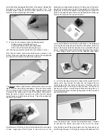
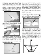
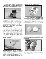
1) The ailerons are now hinged to the trailing edge of the wing.
The supplied hinges are the CA type. Remove the ailerons from
each wing panel, keeping the left aileron with the left wing panel
and the right aileron with the right panel. Remove the eight (8)
hinges. Note that the method used for hinging the ailerons is the
same method that will be used to hinge the rudder and elevators.
The hinges have a die-cut center in them that can be used to
accurately place and center the hinge equally into both the wing
panel and the aileron. To do this, use a business card and a pair
of scissors to cut eight or so "wedges". These should be wide
enough at the top so as to not pass through the cut out in the
center of the hinge.
Press the hinges into the pre-cut hinge
slots in the wing panel up to the hinge slot cut out. Place a card
wedge into each hinge center and then press the aileron in place
onto each exposed hinge half, up to the card wedges. Align the
outer tip of the aileron with the wing panel tip. The hinges are now
in proper position for permanently gluing in place with thin CA
glue.
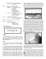
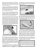
Flex the aileron downward about 30
O
or so, exposing both sides
of each hinge between the wing and aileron. Use a piece of
masking tape to hold the aileron in this position. For CA hinges,
we always suggest using a fine-tipped applicator on the glue
bottle to have better control of the flow. Remove the wedge from
one of the hinges and apply four small drops of thin CA glue to
each hinge edge. Remove the wedge from the next hinge and
again apply four drops of glue to each hinge edge. Repeat this
process for the remaining two hinges. Remove the tape holding
the flexed aileron to the wing panel and flex the aileron in the
opposite direction, again taping it to the wing to hold it in position.
Turn the wing over and apply four drops of thin CA glue to each
edge of the exposed hinges. Remove the tape and return the
aileron to its neutral position. It takes about 10 minutes for the CA
glue to fully wick its way across the surface of the hinge. Clean off
any spilled glue with SIG Debonder.
After sufficient time has passed, flex the aileron firmly up and
down on the wing panel to create free and easy movement. We
also suggest pulling on the aileron at each hinge location to be
sure that they are firmly in place. Repeat this procedure to hinge
the opposite aileron in place.
❑
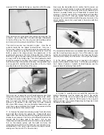
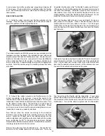
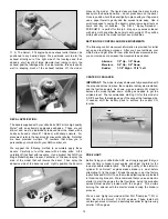
2) Each aileron has two pre-drilled control horn mounting
holes at their leading edges, directly behind the aileron servo
openings. From the kit contents, locate the two plastic control
horns. Note that the control horns are to be mounted on the
bottom of each aileron, facing forward to the aileron servo
openings. Use thick CA glue for this step. Apply a small amount
of glue to each of the two "spikes" on the control horn. Apply an
additional dab of glue to the base of the control horn, between the
two "spikes".
Press the two control horn spikes into the two