❑
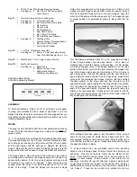
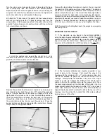
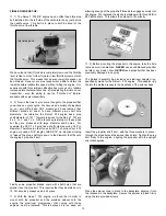
2) The Wheel Pants are now installed to the aluminum main
landing gear. Note that in side view, the landing gear is tapered
on one edge. The front or leading edge of the landing gear is the
untapered edge. Prepare the mounting holes in each wheel pant
by drilling a small diameter pilot hole (.052, #55 bit) through the
factory mark in the pant and the plywood pad inside. Mount the
pant to the landing gear using a 9mm PWA screw. Mount the
remaining pant in the same manner. After establishing the threads
with the mounting screws, we suggest removing the screws and
"hardening" the threads in each wheel pant with a small drop of
thin CA glue. After the glue sets, re-establish the threads once
again with the screws. This protects the threads from fuel damage
and makes them more resistant to stripping.
❑
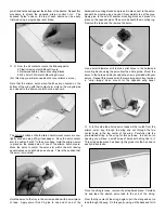
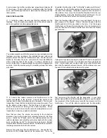
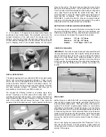
3) The main landing gear assembly is now mounted to the
bottom of the fuselage, using the two M3 x 10mm PWA bolts
and the two M3 Split Ring washers provided.
It is highly
recommended that you first apply a small amount of non-
permanent thread locking compound, such as Loctite
®
#242
"Blue", to the bolt threads.
LANDING GEAR AND WHEEL PANTS:
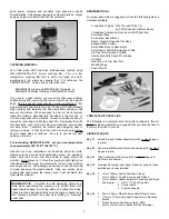
From the kit contents, locate the bag containing the two Wheel
Pants and the bag containing the aluminum Main Landing Gear,
the Main Wheels, and the smaller bag of Mounting Hardware.
❑
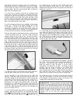
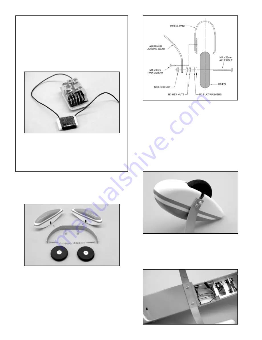
1) Slide one of the M3 x 2mm Axle Bolts through one of the
main wheels. One the other side of the wheel, slide two M3 Flat
Washers in place. Thread one of the M3 Hex Nuts in place almost
up to the wheel hub. Thread a second M3 Hex Nut in place up to
the first nut. Use pliers or a metric box end wrench to hold one of
the M3 nuts while firmly tightening the second nut to it - make sure
the wheel turns freely. Slide the exposed end of the M3 Axle Bolt
through the bottom hole in the aluminum Main Landing Gear.
Start to thread one of the M3 Lock Nuts onto the Axle Bolt. Hold
the nut firmly with pliers or a wrench and use a screwdriver to
tighten the axle bolt assembly firmly in place to the landing gear.
Repeat this process with the remaining wheel.
12
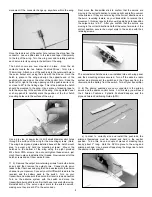
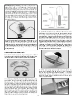
MODELER'S TIP (continued): We made our "bobbin" from a
piece of 3/32" x 3/4" x 1-1/4" balsawood. From the receiver,
measure the antenna out to 4-1/2" - no closer. This is the point
to start neatly wrapping the antenna wire around the bobbin. Do
not cross the wrapped antenna wire, simply lay it neatly next to
each strand. Wrapping the antenna wire 12 - 14 times around
a bobbin this size shortens its overall length by about 11". Hold
the now wrapped antenna wire to the bobbin with a length of
clear tape. Now when you install the receiver into the fuselage,
you will have a much more reasonable length of antenna wire to
work with at the rear.
What will this procedure do to the range of your receiver? The
answer is that you will lose some amount of range but not
enough to effect the overall safe operation of the model. This is
because a small R/C model is rarely flown to extreme distances
for the simple reason that you can no longer see it. Since you
would never do this, some loss of range is more than acceptable
for a small model.


