background image

WARRANTY

Great Planes

®

Model Manufacturing Co. guarantees this kit to be free from defects in both material and workmanship at the date of

purchase. This warranty does not cover any component parts damaged by use or modification. In no case shall Great Planes' liability
exceed the original cost of the purchased kit. 
Further, Great Planes reserves the right to change or modify this warranty without notice.

In that Great Planes has no control over the final assembly or material used for final assembly, no liability shall be assumed nor
accepted for any damage resulting from the use by the user of the final user-assembled product. By the act of using the user-assembled
product, the user accepts all resulting liability.

If the buyer is not prepared to accept the liability associated with the use of this product, the buyer is advised to return this
kit immediately in new and unused condition to the place of purchase.

READ THROUGH THIS  MANUAL  BEFORE
STARTING CONSTRUCTION. IT CONTAINS
IMPORTANT WARNINGS AND INSTRUCTIONS
CONCERNING THE ASSEMBLY AND USE OF
THIS MODEL.

GPMZ0282 for GPMA1326  V1.0

© Copyright 2003

Champaign, Illinois

(217) 398-8970, Ext 5

[email protected]

INSTRUCTION MANUAL

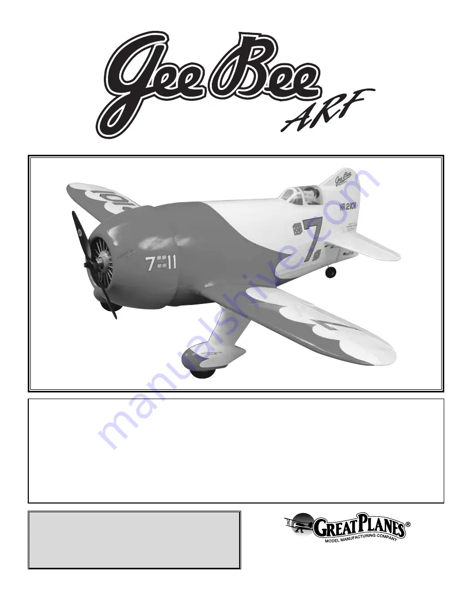
Wingspan: 68 in [1727mm] 
Wing Area: 743 sq in [48 dm

2

Weight: 11-1/4 - 12-1/4 lbs [5103 - 5557 g]
Wing Loading: 34.9 - 38 oz/sq ft [106 - 116 g/dm2]
Length: 45 in [1143mm] 
Radio: 4 channel with six servos
Engine: .91 - 1.08 cu in [15cc - 18cc] two-stroke,1.20 cu in [20 cc] four-stroke

Содержание Gee Bee

Страница 1: ...product By the act of using the user assembled product the user accepts all resulting liability If the buyer is not prepared to accept the liability associated with the use of this product the buyer is advised to return this kit immediately in new and unused condition to the place of purchase READ THROUGH THIS MANUAL BEFORE STARTING CONSTRUCTION IT CONTAINS IMPORTANT WARNINGS AND INSTRUCTIONS CONC...

Страница 2: ...ormation or changes to this model a tech notice box will appear in the upper left corner of the page http www greatplanes com airplanes index html Though the Great Planes Gee Bee is an ARF and may not have the same level of detail as an all out scratch built competition model it is a scale model nonetheless and is therefore eligible to compete in the Fun Scale class in AMA competition We receive m...

Страница 3: ...orial Drive Muncie IN 47302 9252 Tele 800 435 9262 Fax 765 741 0057 Or via the Internet at http www modelaircraft org This is a partial list of items required to finish the Gee Bee that may require planning or decision making before starting to build 4 Channel transmitter and a minimum 4 channel receiver A 6 channel computer radio transmitter and receiver may offer some mixing functions desirable ...

Страница 4: ...structions it means that you should first position the part on the assembly without using any glue then slightly modify or custom fit the part as necessary for the best fit Whenever the term glue is written you should rely upon your experience to decide what type of glue to use When a specific type of adhesive works best for that step the instructions will make a recommendation Whenever just epoxy...

Страница 5: ...rts and the work area thoroughly after working with fiberglass parts IMPORTANT INFORMATION ABOUT WORKING WITH FIBERGLASS To order replacement parts for the Great Planes Gee Bee ARF use the order numbers in the Replacement Parts List that follows Replacement parts are available only as listed Not all parts are available separately an aileron cannot be purchased separately but is only available with...

Страница 6: ... 6 32 x 1 4 SHCS 2 4 40 Set Screw 1 4 40 x 1 4 SHCS 4 6 32 x 1 2 SHCS 8 4 x 5 8 SMS 8 8 32 x 1 SHCS 34 2 x 1 2 SMS 3 Heat Shrink Tube 2 1 8 Wheel Collar 4 5 32 Wheel Collar 3 074 x 17 1 2 wire 3 074 x 6 wire 4 6 Flat Washer 8 8 Lock washer 8 8 Flat Washer 2 Axles 4 3 x 51 x 51mm Plywood Plate 4 3mm Plywood Cowl Mount Tabs 18 1 8 x 3 4 Aluminum Tube 1 Pilot Kit Contents Photographed Kit Contents No...

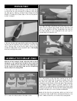
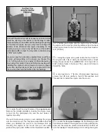
Страница 7: ...components of the foam cradle 2 Slide the foam part with the large oval onto one end of each of the two plastic pipes Slide the part with the small oval on the opposite end This configuration will hold the Gee Bee upright on your workbench and work well for transporting your Gee Bee too 3 For working on the Gee Bee inverted on the bench remove the foam parts from the pipes and replace them with th...

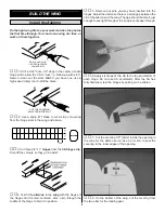
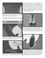
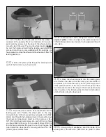
Страница 8: ...pin through the middle of the hinge to hold it in position 5 Remove any pins you may have inserted into the hinges Adjust the aileron so there is a small gap between the LE of the aileron and the wing The gap should be small just enough to see light through or to slip a piece of paper through 6 Apply six drops of thin CA to the top and bottom of each hinge Do not use CA accelerator After the CA ha...

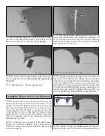
Страница 9: ...ileron servo Secure the connectors together using a large piece of heat shrink tubing tape or other method for securing the connectors together 3 Tie the string from inside the wing to the end of the servo wire Pull the servo wire through the wing with the string Feed the servo wire out the hole in the top of the wing center section Tape the servo wire to the wing to prevent it from falling back i...

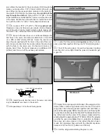
Страница 10: ...gree bend From the bend measure an additional 3 16 4 8mm and then cut off the excess pushrod wire 8 Install the wire into the hole in the servo arm using a nylon FasLink as shown in the sketch 9 Repeat steps 1 8 for the left wing panel 1 Locate the three hardwood wing joiners Using 5 minute epoxy glue them together forming one 1 4 6mm wing joiner 2 Test fit the wing joiner into each wing panel mak...

Страница 11: ...ood rail under the covering Insert a 2 x 1 2 13mm screw into each of the holes you have drilled and then remove it Put a couple of drops of thin CA into the holes to harden the wood and allow the glue to cure Install each of the landing gear straps over the landing gear wire with 2 x 1 2 13mm sheet metal screws 3 Locate the right side wheel pant Note If you examine the base of the two wheel pants ...

Страница 12: ...Insert and then remove a 4 x 5 8 15 9mm sheet metal screw into each of the four holes you have drilled in the wing Put a couple of drops of thin CA into the holes and allow the glue to cure Once the glue has cured install the wheel pant to the wing with four 4 x 3 8 9 5mm sheet metal screws 8 Locate two 1 8 x 3 8 x 3 8 3mm x 51mm x 51mm plywood plates From one edge of the plate measure in 7 8 22 2...

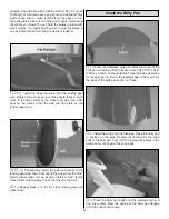
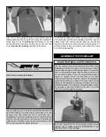
Страница 13: ...ing gear wire File a flat spot on the wire where the 5 32 4mm wheel collar will be located Install a 5 32 4mm wheel collar onto the axle to lock the wheel to the axle 13 Repeat steps 1 12 for the other landing gear and wheel pant 1 Locate the fiberglass belly pan Mark the center of the belly pan on the face of the belly pan Cut a notch 5 16 x 5 16 7 9mm x 7 9mm on the centerline This will provide ...

Страница 14: ...with rubbing alcohol After the alcohol has dried glue the belly pan to the wing with 6 minute epoxy You will find it easier to glue one side at a time rather than trying to do both sides together If you are using the O S 91 two stroke engine you will need to use a muffler extension OSMG2582 to help clear the bottom of the fuselage You now need to make a few decisions about the engine installation ...

Страница 15: ...ck washers four 8 flat washers and Thread Lock to install the engine onto the mount 5 Locate the fiberglass fuselage On the firewall you will find reference marks for the engine mount Using a felt tip pen draw over the reference marks and extend them further out onto the fuselage This will assist you in mounting the engine Even with the extension it will be necessary to make a small clearance open...

Страница 16: ...f this is the case with your engine re install the engine to the mount after the mount is attached to the fuselage Leave the bolts slightly loose Center the engine on the firewall and then tighten the bolts 9 Locate the die cut 3mm plywood parts for constructing the throttle servo tray Glue them together as shown 10 Drill four 1 16 1 6mm mounting holes in the servo tray for the throttle servo Thre...

Страница 17: ...3 16 4 8mm extending from the bend Install a brass quick connect onto the throttle arm using the nylon retainer Enlarge the first hole in the servo arm with a Hobbico Servo Horn Drill or a 48 or 5 64 2mm drill bit Insert the straight end of the wire into the hole in the brass quick connect Insert the opposite end through the hole in the servo arm Install a nylon Faslink onto the servo arm and then...

Страница 18: ...it for filling the tank The method you use is your choice but make your decision before moving onto the installation of the fuel tank You may already have discovered that the Gee Bee stands on its tail pretty well For the installation of the cowl you will find it helpful to stand the fuselage on its tail Temporarily slide the stab into place in the fuselage This will aid standing it on the tail Pl...

Страница 19: ...stalling the cowl 8 With the cowl ring still being held in place with the clamps on one tab measure 1 2 13mm from the outer edge of the cowl ring towards the fuselage Make this mark in the center of the tab On the mark drill through the ring and the mounting tab with a 1 16 1 6mm drill bit Remove the clamp and screw a 2 x 1 2 sheet metal screw through the cowl ring and into the mounting tab Repeat...

Страница 20: ...ith a fuel proof paint Paint the cylinders and the area around them flat black and the engine case a light gray After the paint is dry insert the aluminum tubes into the dummy engine Hold them in place by applying a small amount of epoxy to each tube on the back side of the dummy engine You can add additional detail to the dummy engine by drilling a small hole in each cylinder to accept the spark ...

Страница 21: ... cowl to determine exactly where any holes may have to be drilled When you have finished remove the cowl 22 With the fuselage standing on its tail place the dummy engine over the engine Then place the cowl over the dummy engine Attach the cowl to the fuselage with the four socket head cap screws To position the dummy engine you will need two 9 229mm balsa sticks and two small rubber bands not incl...

Страница 22: ...stab saddle Double check the alignment of the stab to the wing before the glue cures You can clean any excess epoxy from the fuselage and stab with rubbing alcohol anytime before the glue cures Note Do not be too concerned about getting a large amount of epoxy between the stab and the stab saddle Just get enough glue into the joint to hold it in place In the next step you will remove the wing and ...

Страница 23: ...with the trailing edge of the fuselage Remove the rudder and put a couple of drops of thin CA into the hole to harden the wood After the glue has cured re insert the rudder onto the tailwheel wire to be sure everything still fits well 14 Install three CA hinges using the same method as used for the ailerons Mix a small amount of 6 minute epoxy Work some epoxy into the hole you drilled in the rudde...

Страница 24: ...box 1 1 2 38mm Make a reference mark for positioning the servo tray when gluing it in place Glue the servo tray to the plywood formers and the fuselage 4 Position the battery receiver tray inside the fuselage as shown Make reference marks inside the fuselage identifying where the formers contact the fuselage Sand the areas where the formers will contact the fuselage with 220 grit sandpaper Then wi...

Страница 25: ...e into the hole in the dowel Glue the wire to the groove with a small amount of medium CA 12 Locate one of the 2 3 8 60mm long pieces of heat shrink tubing Cut it in half Slide one piece over the wire and the dowel Then shrink the tubing tightly to the dowel and wire The tubing can be shrunk with either a modeling heat gun or a match 13 From the leftover 074 x 17 1 2 444mm wire cut a 7 1 2 190mm l...

Страница 26: ...0mm long pieces of heat shrink tubing Cut it in half Slide one piece over the wire and the dowel and shrink the tubing tightly to the dowel and wire 30 From the leftover 074 x 17 1 2 444mm wire cut an 8 203mm long wire Make a 90 degree bend 1 4 6mm from the end of the wire Insert the wire into the hole in the dowel Glue the wire to the groove with a small amount of medium CA After the glue has cur...

Страница 27: ...r in position with 64 rubber bands on the battery receiver tray in the top of the fuselage 37 Connect a Y harness to the aileron servo wires in the wing Secure the connections with heat shrink tubing tape or clips intended for that purpose Install a 12 aileron extension to the receiver for the ailerons 38 Mount the receiver on off switch A Great Planes Switch Charge Jack Mounting Set GPMM1000 not ...

Страница 28: ...hem in soap water allows accurate positioning and reduces air bubbles underneath 6 Position decal on the model where desired Holding the decal down use a paper towel to wipe most of the water away 7 Use a piece of soft balsa or something similar to squeegee remaining water from under the decal Apply the rest of the decals the same way 1 Turn on the transmitter and receiver and center the trims If ...

Страница 29: ...ding onto the rods 2 3 4 70mm This is where your model should balance For the Gee Bee we do not recommend that you move the C G forward or back from this point In our testing we found that moving the C G too far aft causes the plane to snap with the recommended elevator control throw Moving the C G forward did not add to the overall stability of the plane and only caused the plane difficulties whi...

Страница 30: ... 1 With the wing level have an assistant help you lift the model by the engine propeller shaft and the bottom of the fuse under the TE of the fin Do this several times 2 If one wing always drops when you lift the model it means that side is heavy Balance the airplane by adding weight to the other wing tip An airplane that has been laterally balanced will track better in loops and other maneuvers N...

Страница 31: ...safe place away from high heat sparks or flames as fuel is very flammable Do not smoke near the engine or fuel and remember that engine exhaust gives off a great deal of deadly carbon monoxide Therefore do not run the engine in a closed room or garage Get help from an experienced pilot when learning to operate engines Use safety glasses when starting or running engines Do not run the engine in an ...

Страница 32: ...orce holes for wood screws with thin CA where appropriate servo mounting screws cowl mounting screws etc 10 Confirm that all controls operate in the correct direction and the throws are set up according to the manual 11 Make sure there are silicone retainers on all the clevises and that all servo arms are secured to the servos with the screws included with your radio 12 Secure connections between ...

Страница 33: ...ing the throttle to see how the model handles at slower speeds Add power to see how she climbs as well Continue to fly around executing various maneuvers and making mental notes or having your assistant write them down of what trim or C G changes may be required to fine tune the model so it flies the way you like Mind your fuel level but use this first flight to become familiar with your model bef...

Страница 34: ...finding that you ve run out of time altitude or airspeed Every maneuver should be deliberate not impulsive For example if you re going to do a loop check your altitude mind the wind direction anticipating rudder corrections that will be required to maintain heading remember to throttle back at the top and make certain you are on the desired rates high low rates A flight plan greatly reduces the ch...

Страница 35: ...MPLATE FOR THE O S 1 20 4 STROKE ENGINE IT WILL USE 8 32 BOLTS AND BLIND NUTS IN A TYPICAL INSTALLATION 1 85 1 85 EM6012 BOLT TEMPLATE FOR THE O S 91 2 STROKE ENGINE IT WILL USE 8 32 BOLTS AND BLIND NUTS IN A TYPICAL INSTALLATION ...

Отзывы: